42 Wyniki
Wyświetl wyniki:
Sortuj według:

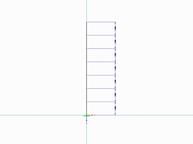
Dzięki rozszerzeniu Projektowanie konstrukcji stalowych możliwe jest projektowanie konstrukcji stalowych zgodnie z normą AISC 360-22. W poniższym artykule porównano wyniki obliczeń zwichrzenia zgodnie z rozdziałem F z analizą wartości własnych.

W rozszerzeniu Projektowanie konstrukcji stalowych dla programu RFEM 6 dostępne są trzy typy ram sprężystych (zwykłe, pośrednie i specjalne). Wyniki obliczeń sejsmicznych zgodnie z AISC 341-22 są podzielone na dwie sekcje: wymagania dotyczące prętów i połączeń.

Rozszerzenie Projektowanie konstrukcji stalowych w RFEM 6 oferuje teraz możliwość przeprowadzania obliczeń sejsmicznych zgodnie z AISC 341-16 i AISC 341-22. Obecnie dostępnych jest pięć typów systemów sejsmicznych (SFRS).

W rozszerzeniu Projektowanie konstrukcji stalowych dla programu RFEM 6 dostępne są trzy typy ram sprężystych (zwykłe, pośrednie i specjalne). Wyniki obliczeń sejsmicznych zgodnie z AISC 341-16 są podzielone na dwie sekcje: wymagania dotyczące prętów i połączeń.

Obliczanie ramy momentowej zgodnie z AISC 341-16 jest teraz możliwe w rozszerzeniu Projektowanie konstrukcji stalowych dla programu RFEM 6. Wynik obliczeń sejsmicznych jest podzielony na dwie sekcje: wymagania dotyczące prętów i połączeń. W tym artykule omówiono wymaganą wytrzymałość połączenia. Przedstawiono przykładowe porównanie wyników pomiędzy RFEM a AISC Seismic Design Manual.

Obliczenia zwykłej ramy stężonej koncentrycznie (OCBF) oraz SCBF (specjalnej konstrukcji szkieletowej stężonej koncentrycznie) można przeprowadzić w rozszerzeniu Projektowanie konstrukcji stalowych dla programu RFEM 6. Wyniki obliczeń sejsmicznych zgodnie z AISC 341-16 i 341-22 są podzielone na dwie sekcje: Wymagania dotyczące prętów i połączeń.

Zarówno analiza drgań własnych, jak i analiza spektrum odpowiedzi przeprowadzane są na układzie liniowym. Jeżeli w modelu występują nieliniowości, podlega on linearyzacji, dzięki czemu elementy nieliniowe nie są brane pod uwagę w dalszej analizie. Mogą to być na przykład pręty rozciągane, podpory nieliniowe lub przeguby nieliniowe. W tym artykule pokazano, w jaki sposób można nimi zarządzać w analizie dynamicznej.
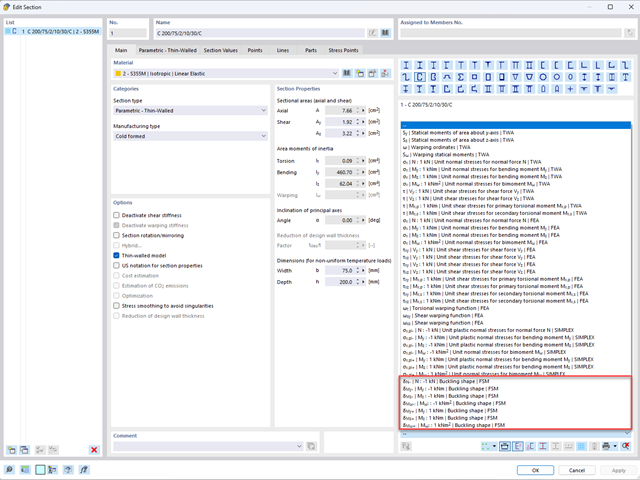
Aby umożliwić ocenę wpływu lokalnych zjawisk stateczności smukłych elementów, w programach RFEM 6 i RSTAB 9 można przeprowadzić liniową analizę obciążenia krytycznego na poziomie przekroju. Poniższy artykuł poświęcony jest podstawom obliczeń i interpretacji wyników.

Wymiarowanie prętów stalowych formowanych na zimno zgodnie z AISI S100-16 jest teraz dostępne w programie RFEM 6. Design can be accessed by selecting “AISC 360” as the standard in the Steel Design add-on. “AISI S100” is then automatically selected for the cold-formed design (Image 01).

Osłony przeciwwiatrowe to specjalne konstrukcje tekstylne, które mają za zadanie chronić środowisko przed szkodliwymi cząsteczkami chemicznymi, jak również ograniczać erozję wietrzną, przyczyniając się do ochrony cennych zasobów. RFEM i RWIND są używane do analizy konstrukcji wiatrowej dla jednostronnej interakcji płyn-konstrukcja (FSI).
W tym artykule pokazano, jak wymiarować osłony przeciwwiatrowe przy użyciu programów RFEM i RWIND.
W tym artykule pokazano, jak wymiarować osłony przeciwwiatrowe przy użyciu programów RFEM i RWIND.

Zaletą modułu dodatkowego RFEM 6 Steel Joints jest możliwość analizy połączeń stalowych przy użyciu modelu MES, dla którego modelowanie przebiega w pełni automatycznie w tle. Elementy składowe złącza stalowego, które kontrolują modelowanie, można wprowadzić, definiując je ręcznie lub korzystając z dostępnych szablonów w bibliotece. Ta ostatnia metoda została opisana w poprzednim artykule z Bazy wiedzy zatytułowanym „Definiowanie komponentów połączenia stalowego przy użyciu biblioteki”. Definiowanie parametrów do wymiarowania połączeń stalowych jest tematem artykułu w bazie wiedzy „Projektowanie połączeń stalowych w RFEM 6”.

W tym artykule technicznym omówimy podstawowe kwestie dotyczące korzystania z rozszerzenia Skręcanie skrępowane (7 stopni swobody). Jest ono w pełni zintegrowane z programem głównym i umożliwia uwzględnienie deplanacji przekroju podczas obliczania elementów prętowych. W połączeniu z rozszerzeniami Analiza stateczności oraz Wymiarowanie stali, możliwe jest przeprowadzenie obliczeń wyboczenia giętno-skrętnego z siłami wewnętrznymi zgodnie z analizą drugiego rzędu oraz uwzględnieniem imperfekcji.
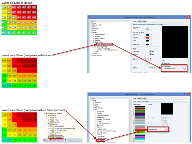
Um eine übersichtlichere Darstellung der Ergebniswerte zu erzielen, können verschiedene Einstellungen vorgenommen werden. Einige Anwender stört beispielsweise der weiße Hintergrund in den Textblasen. Dieser Hintergrund kann in den "Anzeigeeigenschaften" über die Transparenz und über die Hintergrundfarbe gesteuert werden.
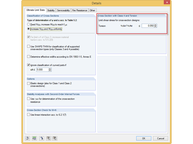
Häufig verhindern sehr kleine Torsionsmomente in den zu bemessenden Stäben bestimmte Nachweisformate. Um diese zu vernachlässigen und die Nachweise dennoch zu führen, kann man in RF-/STAHL EC3 einen Grenzwert definieren, ab dem Torsionsschubspannungen berücksichtigt werden.
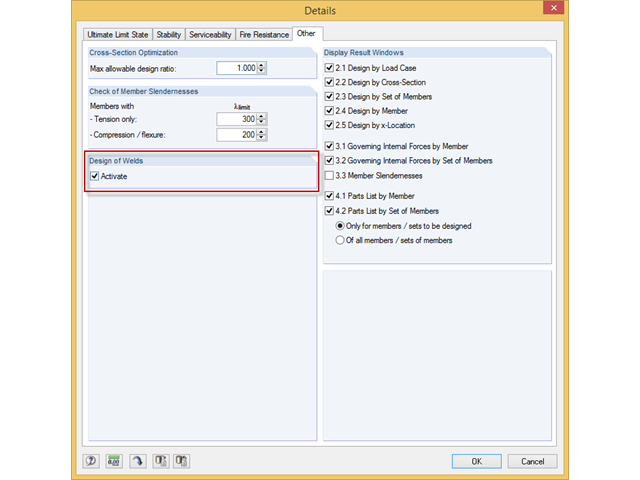
Das Zusatzmodul RF-/STAHL EC3 kann den Nachweis der Halskehlnähte für alle parametrischen, geschweißten Querschnitte der Querschnittsbibliothek führen. Hierzu muss die Option in den Detaileinstellungen des Moduls aktiviert werden. Alternativ kann auch ein Flächenmodell zur Bemessung genutzt werden.
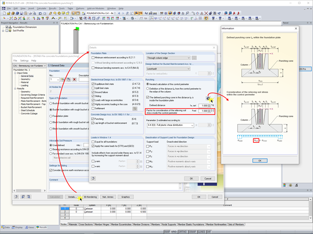
In RF-/FUND Pro hat der Anwender die Möglichkeit, den Anteil der entlastenden Bodenpressungen mittels des Faktors kred frei zu wählen.
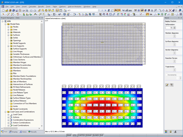
W przypadku stosunkowo dużych i stosunkowo małych powierzchni, może się zdarzyć, że automatycznie utworzone wartości wyników nie będą pasowały do modelu: Die Ergebnisse werden bei großen Flächen entweder zu häufig erzeugt oder bei kleinen Flächen zu wenig.
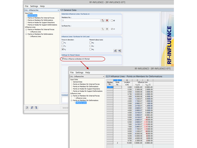
Standardmäßig werden die ermittelten Werte für die Ordinaten der Einflusslinie als Dezimalzahl mit maximal sechs Nachkommastellen ausgegeben. Für die Einflusslinien der Schnittgrößen ist dies meist ausreichend.
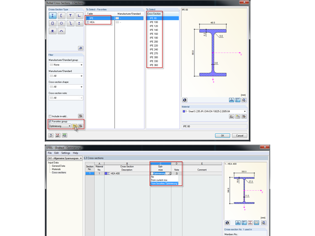
Bei der Querschnittsoptimierung in den Zusatzmodulen können auch beliebig definierte Querschnitts-Favoritenlisten ausgewählt werden - zusätzlich zu den Profilen aus der gleichen Profilreihe wie das ursprüngliche Profil.
Mit RF-/DYNAM Pro Ersatzlasten ist es möglich, eine Ersatzlastberechnung anhand des multimodalen Antwortspektren-Verfahrens zu durchzuführen. Im dargestellten Beispiel wurde dies für einen Mehrmassenschwinger durchgeführt.
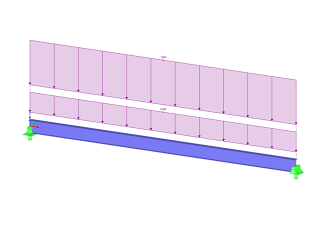
Moduł dodatkowy RF-STEEL AISC umożliwia wymiarowanie prętów stalowych zgodnie z normą AISC 360-16. W poniższym artykule technicznym porównano wyniki obliczeń zwichrzenia zgodnie z rozdziałem F i wyniki pochodzące z analizy wartości własnych.
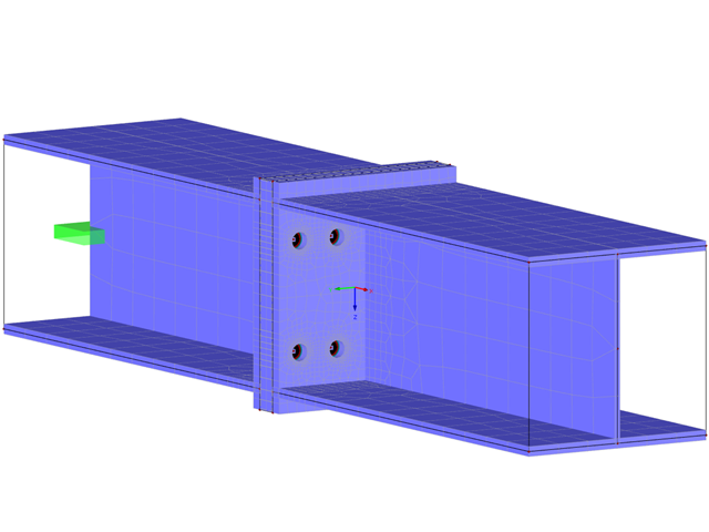
Projektowanie sztywnych połączeń z blachami czołowymi jest szczególnie skomplikowane w przypadku geometrii połączeń gdzie występują cztery łączniki w jednym rzędzie oraz dwukierunkowe zginanie, ponieważ nie istnieją oficjalne wytyczne do wymiarowania tego typu detali.
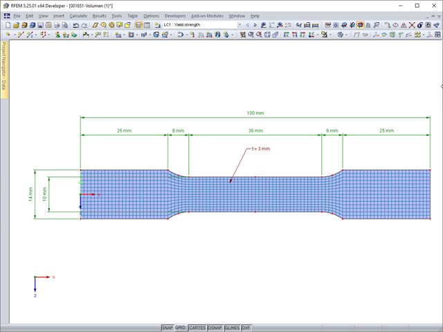
Deformacje sprężyste elementu konstrukcyjnego pod wpływem obciążenia są oparte na prawie Hooke'a, opisującym liniową zależność naprężenie-odkształcenie. Są one odwracalne: po odciążeniu element powraca do swojego pierwotnego kształtu. Jednakże deformacje plastyczne są nieodwracalne i zazwyczaj znacznie większe niż odkształcenia sprężyste. W przypadku naprężeń plastycznych materiałów ciągliwych, takich jak stal, efekty plastyczności występują w miejscach, w których wzrostowi odkształceń towarzyszy zjawisko lokalnego wzmocnienia. Prowadzi to do powstania trwałych deformacji, a w ekstremalnych przypadkach do zniszczenia elementu konstrukcyjnego.
Europejska norma EN 1993-1-8, sekcja 4.5.3.3. umożliwia zastosowanie uproszczonej metody obliczania stanu granicznego nośności spoin pachwinowych. Zgodnie z normą warunki nośności można uznać za spełnione, jeżeli wartość obliczeniowa wypadkowej oddziałującej na obszar spoiny pachwinowej jest mniejsza niż wartość obliczeniowa nośności spoiny. Jeśli więc wymiarowanie spoiny ma zostać przeprowadzone na bazie wyników z modelu powierzchniowego, użytkownik może odczytać liczne typy rezultatów ze względu na charakter obliczeń MES dla powłok. Dlatego w tym artykule pokazujemy, jak określić składowe siły z takiego modelu.
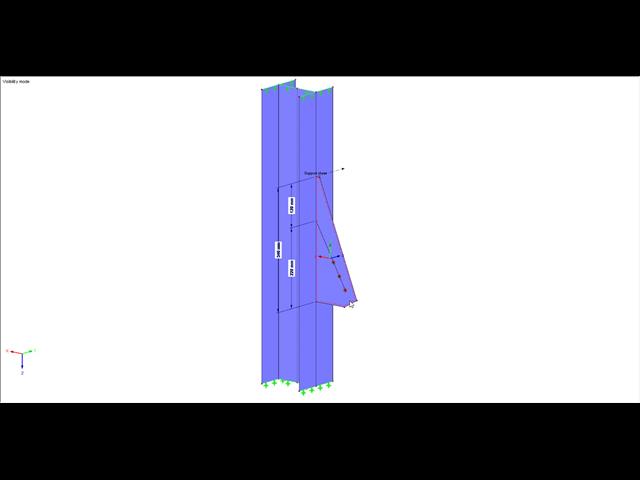
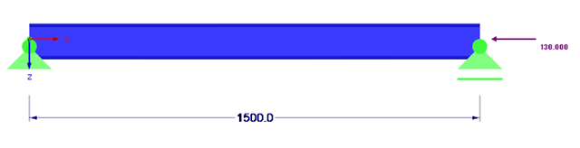
Niniejszy artykuł techniczny omawia analizę stateczności płatwi, która połączona jest z konstrukcją główną tylko poprzez przykręcenie dolnej półki profilu płatwii za pomocą śrub (bez dodatkowego podparcia bocznego). Połączenie takie ma na celu maksymalną redukcję kosztów i czasu produkcji.
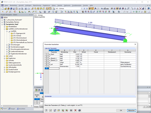
Zgodnie z punktem 3.2.2 normy EN 1993-1-3 możliwe jest zastosowanie podwyższonej średniej granicy plastyczności fya dla przekrojów poprzecznych tam, gdzie dochodzi do efektu dosztywnienia w wyniku powstałego odkształcenia (tzw. strain hardening).
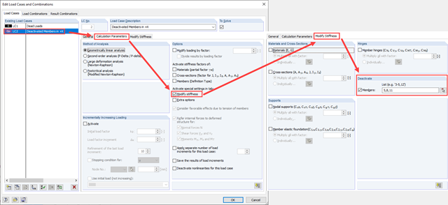
Zarówno analiza drgań własnych, jak i analiza spektrum odpowiedzi przeprowadzane są na układzie liniowym. Jeżeli w modelu występują nieliniowości, podlega on linearyzacji, dzięki czemu elementy nieliniowe nie są brane pod uwagę w dalszej analizie. W praktyce jednak bardzo często wprowadzamy do modeli elementy "tylko rozciągane". W przedstawionym artykule opisano, w jaki sposób można je poprawnie zastąpić dla przeprowadzenia liniowej analizy dynamicznej.
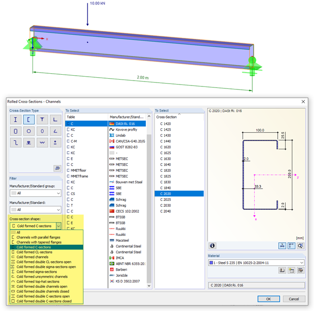
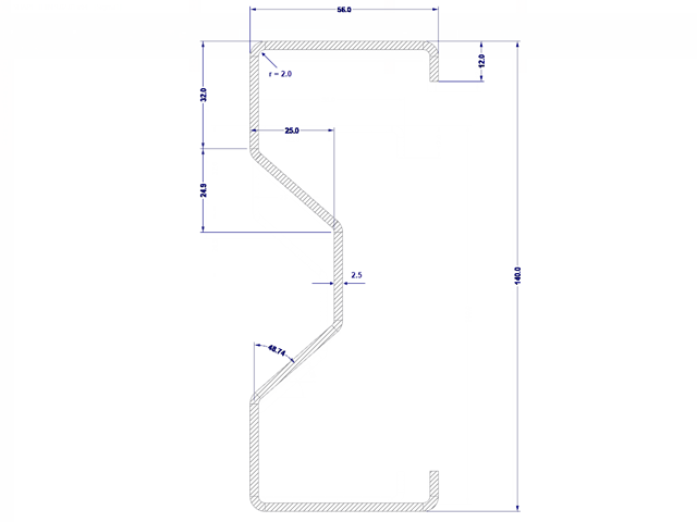
Zasady obliczania stalowych elementów walcowanych na zimno są zdefiniowane w EN 1993-1-3. Typowe kształty przekrojów formowanych na zimno to: ceowniki, zetowniki, kształtowniki kapeluszowe lub sigma. Są to wyroby stalowe wykonywane z cienkich blach w procesie walcowania na zimno lub gięcia. Podczas obliczania stanów granicznych nośności należy dopilnować, aby lokalne siły poprzeczne nie prowadziły w środniku do ściskania, wybrzuszenia, wyboczenia lub innej lokalnej formy utraty stateczności. Efekty te mogą być spowodowane działaniem lokalnych sił poprzecznych na półkę profilu oraz sił reakcji w punktach podparcia. W sekcji 6.1.7 normy EN 1993-1-3 szczegółowo opisano, jak określić nośność środnika Rw, Rd na wpływ działania lokalnych sił poprzecznych.
Obliczenia stanu granicznego nośności przekrojów formowanych na zimno zgodnie z EN 1993-1-3 i EN 1993-1-5 można przeprowadzić za pomocą rozszerzenia RF-/STEEL Cold-Formed Sections. Oprócz profili formowanych na zimno z bazy danych przekrojów, SHAPE-THIN umożliwia także obliczanie przekrojów uogólnionych.
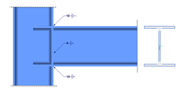
Bemessung einer geschweißten Verbindung eines HEA-Profils unter zweiachsiger Biegung mit Normalkraft. Nachweis der Schweißnähte für die gegebenen Schnittgrößen nach dem vereinfachten Verfahren (DIN EN 1993-1-8 Abs. 4.5.3.3 ) mittels DUENQ.