23 Wyniki
Wyświetl wyniki:
Sortuj według:

Niniejszy artykuł dotyczy długotrwałego ugięcia konstrukcji betonowych zgodnie z ACI 318 i CSA A23.3.

Podczas obliczania regularnych konstrukcji wprowadzanie danych często nie jest skomplikowane, ale czasochłonne. Oszczędzaj cenny czas dzięki automatycznemu wprowadzaniu danych. W niniejszym przypadku należy uwzględnić kondygnacje domu jako poszczególne etapy budowy. Dane są wprowadzane przy pomocy programu w języku C#, aby użytkownik nie musiał ręcznie wprowadzać elementów poszczególnych pięter.

W tym artykule wyjaśniono różne metody dostępne w rozszerzeniu Analiza modalna, służące do określania liczby postaci własnych.

Ocena przemieszczenia kondygnacji w budynku jest kluczowa dla zapewnienia zadowalających parametrów konstrukcyjnych poprzez ograniczenie przemieszczenia kondygnacji. Nadmierne znoszenie może powodować niestateczność systemu i powodować uszkodzenia elementów niekonstrukcyjnych, takich jak ściany działowe. W tym artykule opisano procedurę wyznaczania przemieszczeń międzykondygnacyjnych zgodnie z ASCE 7-22 i rozszerzeniem Model budynku w programie RFEM 6.

Norma ASCE 7-22 [1], rozdz. 12.9.1.6 określa, kiedy efekty P-delta powinny być uwzględniane podczas przeprowadzania analizy modalnego spektrum odpowiedzi dla obliczeń sejsmicznych. W NBC 2020 [2], Wys. 4.1.8.3.8.c jedynie w niewielkim stopniu wymaga uwzględnienia przechyłów spowodowanych interakcją obciążeń grawitacyjnych z konstrukcją odkształconą. Z tego względu podczas przeprowadzania analizy sejsmicznej mogą wystąpić sytuacje, w których efekty drugiego rzędu, znane również jako P-delta, muszą zostać uwzględnione.

W artykule przedstawiono podstawowe pojęcia z zakresu dynamiki konstrukcji i ich roli w projektowaniu konstrukcji sejsmicznych. Duży nacisk kładzie się na wyjaśnienie aspektów technicznych w zrozumiały sposób, aby tematyka była zrozumiała dla czytelników bez dużej wiedzy technicznej.

Artykuł 4.1.8.7 kanadyjskich przepisów budowlanych (NBC) 2020 zawiera jasną procedurę dotyczącą metod analizy trzęsień ziemi. Metoda bardziej zaawansowana, a mianowicie metoda analizy dynamicznej opisana w rozdziale 4.1.8.12, powinna być stosowana dla wszystkich typów konstrukcji, z wyjątkiem tych, które spełniają kryteria podane w 4.1.8.7. W przypadku pozostałych konstrukcji, może być stosowana nieco prostsza metoda równoważnych sił statycznych (ESFP), opisana w rozdziale 4.1.8.11.

Aby ocenić, czy w obliczeniach dynamicznych konieczne jest również uwzględnienie analizy drugiego rzędu, w normie EN 1998‑1, sekcje 2.2.2 i 4.4.2.2 zawarto współczynnik wrażliwości międzykondygnacyjnego znoszenia θ. Można ją obliczyć i przeanalizować za pomocą programów RFEM 6 i RSTAB 9.
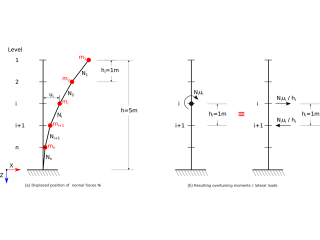
Zgodnie z normami EN 1998-1 sekcje 2.2.2 i 4.4.2.2 do obliczeń stanu granicznego nośności należy przeprowadzić obliczenia z uwzględnieniem teorii drugiego rzędu (efekt P-Δ). Efekt ten nie musi być uwzględniany tylko w przypadku, gdy współczynnik wrażliwości międzykondygnacyjnej jest mniejszy niż 0,1.
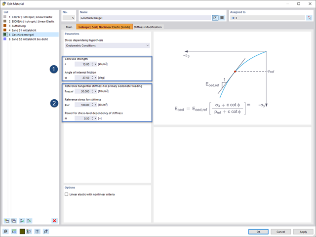
Rozszerzenie Analiza geotechniczna zapewnia programowi RFEM dodatkowe specyficzne modele materiałowe podłoża, które mogą odpowiednio odwzorować złożone zachowanie materiału podłoża. W tym artykule zaprezentujemy, w jaki sposób można określić zależną od naprężeń sztywność modeli materiałowych gruntu.

Zarówno analiza drgań własnych, jak i analiza spektrum odpowiedzi przeprowadzane są na układzie liniowym. Jeżeli w modelu występują nieliniowości, podlega on linearyzacji, dzięki czemu elementy nieliniowe nie są brane pod uwagę w dalszej analizie. Mogą to być na przykład pręty rozciągane, podpory nieliniowe lub przeguby nieliniowe. W tym artykule pokazano, w jaki sposób można nimi zarządzać w analizie dynamicznej.
Modalny współczynnik istotności jest wynikiem analizy stateczności liniowej i opisuje jakościowo stopień udziału poszczególnych prętów w określonym kształcie drgań.

W tym artykule opisujemy, w jaki sposób można używać rozszerzenia Skręcanie skrępowane (7 stopni swobody) i Stateczność konstrukcji w celu uwzględnienia deplanacji przekroju jako dodatkowego stopnia swobody podczas analizy stateczności.
W tym artykule omówiono wyniki analizy geotechnicznej oraz ich graficzne i tabelaryczne przedstawienie w programie RFEM 6.
W tym artykule pokazano praktyczny przykład, jak określać współczynniki obciążenia krytycznego i odpowiadające im kształty drgań w programie RFEM 6.
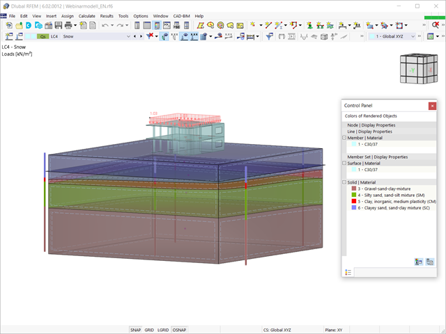
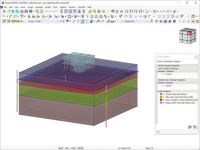
Biorąc pod uwagę, że realistyczne określenie warunków gruntowych znacząco wpływa na jakość analizy statyczno-wytrzymałościowej budynków, w programie RFEM 6 dostępne jest rozszerzenie Analiza geotechniczna, które umożliwia określenie konturu glebowego do analizy.
Sposób udostępnienia danych uzyskanych z badań polowych w rozszerzeniu i wykorzystania właściwości z próbek gruntu do określenia masywów gruntu, które mają być przedmiotem zainteresowania, został omówiony w artykule z Bazy informacji „Tworzenie bryły gruntowej na podstawie próbek gruntu w programie RFEM 6”. W tym artykule omówiono natomiast procedurę obliczania osiadań i parcia gruntu dla budynku żelbetowego.
Sposób udostępnienia danych uzyskanych z badań polowych w rozszerzeniu i wykorzystania właściwości z próbek gruntu do określenia masywów gruntu, które mają być przedmiotem zainteresowania, został omówiony w artykule z Bazy informacji „Tworzenie bryły gruntowej na podstawie próbek gruntu w programie RFEM 6”. W tym artykule omówiono natomiast procedurę obliczania osiadań i parcia gruntu dla budynku żelbetowego.

Analiza dynamiczna w RFEM 6 i RSTAB 9 jest podzielona na kilka rozszerzeń. Rozszerzenie Analiza modalna jest niezbędne dla wszystkich innych rozszerzeń do analizy dynamicznej, ponieważ przeprowadza analizę drgań własnych dla modeli prętów, powierzchni i brył.

Analiza modalna jest punktem wyjścia do analizy dynamicznej układów konstrukcyjnych. Można ją wykorzystać do określenia wartości drgań własnych, takich jak częstotliwości drgań własnych, kształty drgań własnych, masy modalne i efektywne współczynniki masy modalnej. Wynik ten może zostać wykorzystany do obliczeń drgań oraz do dalszych analiz dynamicznych (na przykład obciążenia widmem odpowiedzi).

Jakość analizy statyczno-wytrzymałościowej budynków jest dużo lepsza, gdy można uwzględnić warunki gruntowe w sposób możliwie najbardziej realistyczny. W programie RFEM 6 można realistycznie określić kontur glebowy do analizy za pomocą rozszerzenia Analiza geotechniczna. Ten dodatek można aktywować w danych bazowych modelu, jak pokazano na rysunku 01.
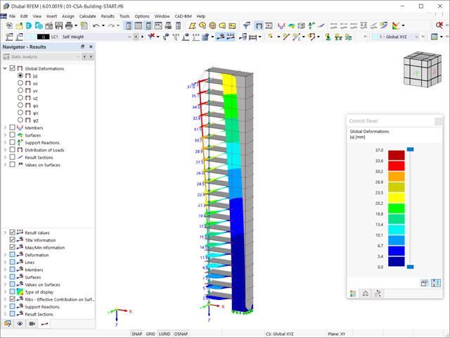
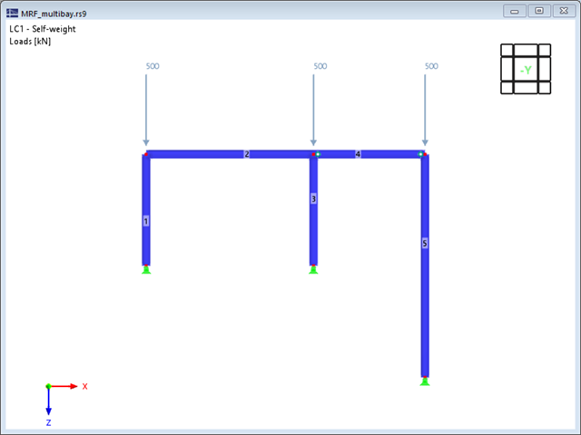
Rozszerzenie Analiza etapów budowy (CSA) umożliwia wymiarowanie konstrukcji prętowych, powierzchniowych i bryłowych w programie RFEM 6 z uwzględnieniem określonych etapów budowy związanych z procesem konstrukcyjnym. Jest to o tyle istotne, że budynki nie powstają w całości od razu, lecz poprzez stopniowe łączenie poszczególnych części konstrukcyjnych. Poszczególne kroki, w których elementy konstrukcyjne oraz obciążenia są dodawane do budynku, nazywane są etapami budowy, podczas gdy sam proces budowy nazywa się procesem konstrukcyjnym.

Obliczenia konstrukcji złożonych za pomocą oprogramowania do analizy elementów skończonych są zazwyczaj przeprowadzane na całym modelu. Jednak wznoszenie tego typu konstrukcji jest procesem wieloetapowym, w którym ostateczny stan konstrukcji uzyskuje się poprzez połączenie poszczególnych elementów konstrukcyjnych. Aby uniknąć błędów w obliczeniach ogólnych modeli, należy wziąć pod uwagę wpływ procesu konstrukcyjnego. W programie RFEM 6 jest to możliwe za pomocą rozszerzenia Analiza etapów budowy (CSA).

Analiza sejsmiczna w programie RFEM 6 jest możliwa przy użyciu rozszerzeń analizy modalnej i analizy spektrum odpowiedzi. Ogólna koncepcja analizy sejsmicznej w programie RFEM 6 opiera się na utworzeniu przypadku obciążenia do analizy modalnej lub analizy spektrum odpowiedzi. Grupy norm dla tych analiz są ustawiane w zakładce Normy II w oknie Dane podstawowe modelu.

W tym artykule technicznym omówimy podstawowe kwestie dotyczące korzystania z rozszerzenia Skręcanie skrępowane (7 stopni swobody). Jest ono w pełni zintegrowane z programem głównym i umożliwia uwzględnienie deplanacji przekroju podczas obliczania elementów prętowych. W połączeniu z rozszerzeniami Analiza stateczności oraz Wymiarowanie stali, możliwe jest przeprowadzenie obliczeń wyboczenia giętno-skrętnego z siłami wewnętrznymi zgodnie z analizą drugiego rzędu oraz uwzględnieniem imperfekcji.