55 Wyniki
Wyświetl wyniki:
Sortuj według:
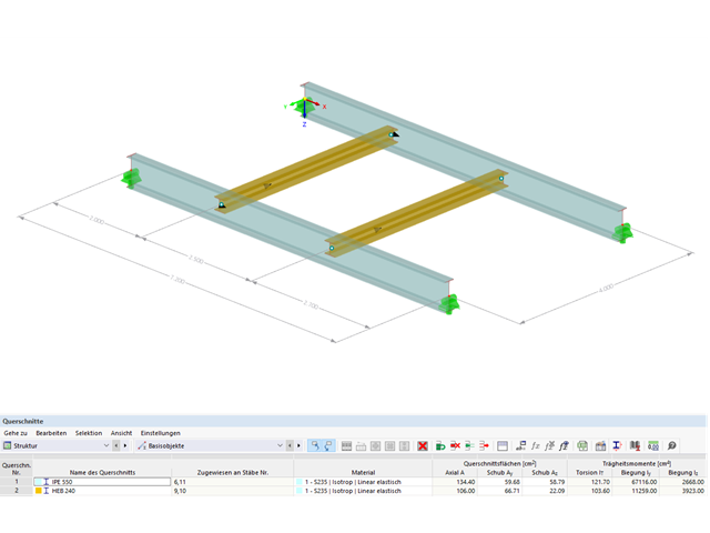
Przykład ten jest opisany w literaturze technicznej [1] jako przykład 9.5 oraz w [2] jako przykład 8.5. Dla podciągu należy przeprowadzić analizę zwichrzenia. Belka jest jednorodnym prętem konstrukcyjnym. Analizę stateczności można zatem przeprowadzić zgodnie z sekcją 6.3.2 normy DIN EN 1993-1-1. Ze względu na zginanie jednoosiowe, możliwe byłoby przeprowadzenie obliczeń również metodą ogólną według rozdz. 6.3.4. Ponadto, na wyidealizowanym modelu pręta należy zweryfikować wyznaczenie współczynnika obciążenia krytycznego w ramach w/w metody z modelem MES.
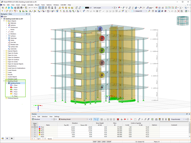
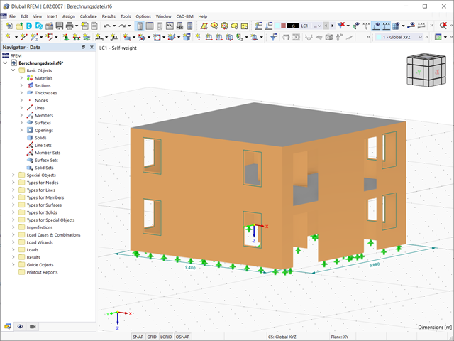
Model budynku jest jednym ze specjalnych rozszerzeń w programie RFEM 6. Jest to przydatne narzędzie do modelowania, za pomocą którego można łatwo tworzyć kondygnacje budynków i nimi manipulować. Model budynku można aktywować na początku procesu modelowania lub po jego zakończeniu.

Jedną z innowacji w programie RFEM 6 jest nowy sposób projektowania połączeń stalowych. W przeciwieństwie do programu RFEM 5, w którym wymiarowanie połączeń stalowych opiera się na rozwiązaniu analitycznym, rozszerzenie Połączenia stalowe w programie RFEM 6 oferuje rozwiązanie dla połączeń stalowych w oparciu o analizę MES.

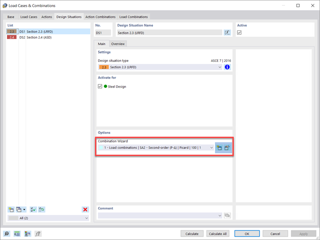
Analiza sejsmiczna w programie RFEM 6 jest możliwa przy użyciu rozszerzeń analizy modalnej i analizy spektrum odpowiedzi. Ogólna koncepcja analizy sejsmicznej w programie RFEM 6 opiera się na utworzeniu przypadku obciążenia do analizy modalnej lub analizy spektrum odpowiedzi. Grupy norm dla tych analiz są ustawiane w zakładce Normy II w oknie Dane podstawowe modelu.
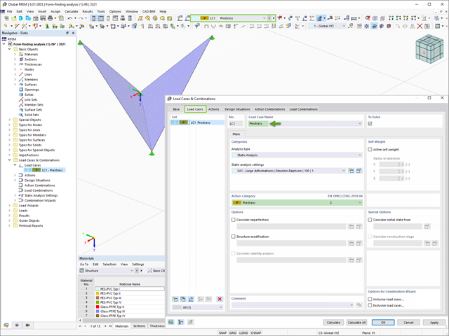
Program RFEM 6 zawiera rozszerzenie Form-Finding do określania kształtów równowagi modeli powierzchni obciążonych rozciąganiem i prętów obciążonych siłami osiowymi. Aktywuj ten dodatek w Danych bazowych modelu i użyj go, aby znaleźć położenie geometryczne, w którym naprężenie wstępne lekkich konstrukcji jest w równowadze z istniejącymi warunkami brzegowymi.

Obliczenia konstrukcji złożonych za pomocą oprogramowania do analizy elementów skończonych są zazwyczaj przeprowadzane na całym modelu. Jednak wznoszenie tego typu konstrukcji jest procesem wieloetapowym, w którym ostateczny stan konstrukcji uzyskuje się poprzez połączenie poszczególnych elementów konstrukcyjnych. Aby uniknąć błędów w obliczeniach ogólnych modeli, należy wziąć pod uwagę wpływ procesu konstrukcyjnego. W programie RFEM 6 jest to możliwe za pomocą rozszerzenia Analiza etapów budowy (CSA).

Nowa generacja oprogramowania RFEM umożliwia przeprowadzanie obliczeń stateczności zbieżnych prętów drewnianych zgodnie z metodą prętów zastępczych. Zgodnie z tą metodą obliczenia można przeprowadzić, jeżeli spełnione są wytyczne normy DIN 1052, sekcja E8.4.2 dla zmiennych przekrojów. W różnych publikacjach technicznych metoda ta jest również stosowana w przypadku Eurokodu 5. W tym artykule pokazano, jak zastosować metodę prętów zastępczych dla belki dachowej o zbieżnej wysokości.

Sprawdzenie stateczności dla wymiarowania prętów zastępczych zgodnie z EN 1993-1-1, AISC 360, CSA S16 i innymi normami międzynarodowymi wymaga uwzględnienia długości obliczeniowej (tj. efektywnej długości prętów). W programie RFEM 6 długość efektywną można określić ręcznie, przypisując podpory węzłowe i współczynniki długości efektywnej lub, z drugiej strony, poprzez import z analizy stateczności. Obie opcje zostaną przedstawione w tym artykule poprzez określenie efektywnej długości słupa obramowanego na rysunku 1.
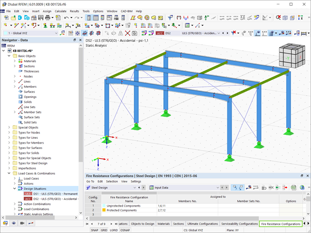
Stal ma słabe właściwości termiczne pod względem ognioodporności. Rozszerzalność termiczna dla wzrastającej temperatury jest bardzo duża w porównaniu z rozszerzalnością innych materiałów budowlanych i może powodować efekty, których nie byłoby w obliczeniach w normalnej temperaturze ze względu na utwierdzenie elementu. Wraz ze wzrostem temperatury wzrasta ciągliwość stali, a jej wytrzymałość maleje. Ponieważ stal traci 50% swojej wytrzymałości w temperaturze 600 °C, ważne jest, aby chronić elementy przed skutkami pożaru. W przypadku zabezpieczonych elementów stalowych, dzięki lepszej reakcji termicznej można wydłużyć ognioodporność.
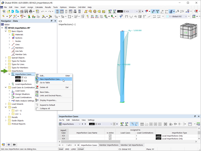
Imperfekcje w inżynierii konstrukcyjnej to odchylenia elementów konstrukcyjnych od ich idealnego kształtu, powstałe podczas produkcji. Są one często wykorzystywane w obliczeniach w celu określenia równowagi sił w elementach konstrukcyjnych w układzie odkształconym.
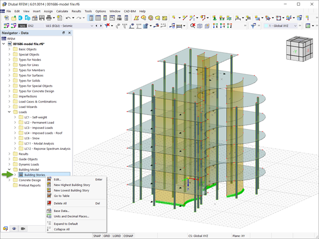
W programie RFEM 6 analizę sejsmiczną można przeprowadzić za pomocą modułów dodatkowych Analiza modalna i Analiza spektrum odpowiedzi. Zaraz po zakończeniu analizy spektralnej za pomocą rozszerzenia Model budynku można wyświetlić oddziaływania kondygnacji, przemieszczenia kondygnacji i siły w ścianach usztywniających.
Norma dotycząca konstrukcji stalowych AISC 360-16 wymaga uwzględnienia stateczności konstrukcji jako całości oraz każdego z jej elementów. Dostępne są różne metody, w tym metoda bezpośredniego uwzględnienia w analizie, metoda długości efektywnej i metoda analizy bezpośredniej. W tym artykule podkreślono ważne wymagania rozdz. C oraz metodę bezpośredniej analizy, która zostanie uwzględniona w modelu konstrukcji stalowej wraz z zastosowaniem w programie RFEM 6.

Rozszerzenie Projektowanie konstrukcji aluminiowych dla RFEM 6 wymiaruje pręty aluminiowe ze względu na stan graniczny nośności i użytkowalności zgodnie z Eurokodem 9. Ponadto możliwe jest wymiarowanie zgodnie z ADM 2020 (norma amerykańska).
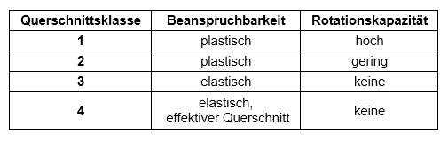
Obliczenia przekrojów zgodnie z Eurokodem 3 opierają się na klasyfikacji projektowanego przekroju według klas określonych w normie. Klasyfikacja przekrojów jest ważna, ponieważ określa granice nośności i nośności obrotowej na skutek wyboczenia lokalnego części przekroju.

Dzięki rozszerzeniu Połączenia stalowe dla RFEM 6 można tworzyć i analizować połączenia stalowe przy użyciu wydzielonego modelu ES. Modelowanie połączeń można kontrolować poprzez proste i wygodne wprowadzanie elementów. Elementy stalowego połączenia można definiować ręcznie lub przy użyciu szablonów dostępnych w bibliotece. Pierwsza metoda została opisana w poprzednim artykule z Bazy wiedzy zatytułowanym „Nowe podejście do wymiarowania połączeń stalowych w programie RFEM 6”. W tym artykule skupimy się na tej drugiej metodzie; tzn. pokaże, jak definiować komponenty połączenia stalowego przy użyciu szablonów dostępnych w bibliotece programu.

W programie RFEM 6 połączenia stalowe definiuje się jako układ elementów. W nowym rozszerzeniu Połączenia stalowe dostępne są podstawowe komponenty do uniwersalnego zastosowania (blachy, spoiny, płaszczyzny pomocnicze). Metody definiowania połączeń opisano w dwóch poprzednich artykułach w Bazie informacji: „Nowe podejście do wymiarowania połączeń stalowych w programie RFEM 6” oraz „Definiowanie elementów połączenia stalowego przy użyciu biblioteki” .

Zaletą modułu dodatkowego RFEM 6 Steel Joints jest możliwość analizy połączeń stalowych przy użyciu modelu MES, dla którego modelowanie przebiega w pełni automatycznie w tle. Elementy składowe złącza stalowego, które kontrolują modelowanie, można wprowadzić, definiując je ręcznie lub korzystając z dostępnych szablonów w bibliotece. Ta ostatnia metoda została opisana w poprzednim artykule z Bazy wiedzy zatytułowanym „Definiowanie komponentów połączenia stalowego przy użyciu biblioteki”. Definiowanie parametrów do wymiarowania połączeń stalowych jest tematem artykułu w bazie wiedzy „Projektowanie połączeń stalowych w RFEM 6”.
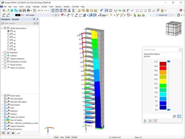
Rozszerzenie Analiza etapów budowy (CSA) umożliwia wymiarowanie konstrukcji prętowych, powierzchniowych i bryłowych w programie RFEM 6 z uwzględnieniem określonych etapów budowy związanych z procesem konstrukcyjnym. Jest to o tyle istotne, że budynki nie powstają w całości od razu, lecz poprzez stopniowe łączenie poszczególnych części konstrukcyjnych. Poszczególne kroki, w których elementy konstrukcyjne oraz obciążenia są dodawane do budynku, nazywane są etapami budowy, podczas gdy sam proces budowy nazywa się procesem konstrukcyjnym.

Jakość analizy statyczno-wytrzymałościowej budynków jest dużo lepsza, gdy można uwzględnić warunki gruntowe w sposób możliwie najbardziej realistyczny. W programie RFEM 6 można realistycznie określić kontur glebowy do analizy za pomocą rozszerzenia Analiza geotechniczna. Ten dodatek można aktywować w danych bazowych modelu, jak pokazano na rysunku 01.
Konstrukcje murowe można modelować i analizować w programie RFEM 6 za pomocą rozszerzenia Projektowanie konstrukcji murowych, który wykorzystuje do obliczeń metodę elementów skończonych. Zakładając, że w programie zaimplementowano nieliniowy model materiałowy, można modelować złożone konstrukcje murowe oraz przeprowadzać analizę statyczną i dynamiczną, aby przedstawić nośność konstrukcji murowej oraz różne mechanizmy uszkodzenia. Istnieje możliwość wprowadzania i modelowania konstrukcji murowych bezpośrednio w programie RFEM 6 oraz łączenia modelu materiałowego muru ze wszystkimi popularnymi rozszerzeniami dla programu RFEM. Umożliwia to projektowanie całych modeli budynków w połączeniu z murem.