24 Wyniki
Wyświetl wyniki:
Sortuj według:

Ocena przemieszczenia kondygnacji w budynku jest kluczowa dla zapewnienia zadowalających parametrów konstrukcyjnych poprzez ograniczenie przemieszczenia kondygnacji. Nadmierne znoszenie może powodować niestateczność systemu i powodować uszkodzenia elementów niekonstrukcyjnych, takich jak ściany działowe. W tym artykule opisano procedurę wyznaczania przemieszczeń międzykondygnacyjnych zgodnie z ASCE 7-22 i rozszerzeniem Model budynku w programie RFEM 6.

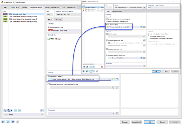
Norma ASCE 7-22 [1], rozdz. 12.9.1.6 określa, kiedy efekty P-delta powinny być uwzględniane podczas przeprowadzania analizy modalnego spektrum odpowiedzi dla obliczeń sejsmicznych. W NBC 2020 [2], Wys. 4.1.8.3.8.c jedynie w niewielkim stopniu wymaga uwzględnienia przechyłów spowodowanych interakcją obciążeń grawitacyjnych z konstrukcją odkształconą. Z tego względu podczas przeprowadzania analizy sejsmicznej mogą wystąpić sytuacje, w których efekty drugiego rzędu, znane również jako P-delta, muszą zostać uwzględnione.
Zgodność z przepisami budowlanymi, takimi jak Eurokod, jest niezbędna dla zapewnienia bezpieczeństwa, integralności konstrukcji i trwałości budynków i konstrukcji. Obliczeniowa mechanika płynów (CFD) odgrywa istotną rolę w tym procesie, symulując zachowanie płynów, optymalizując projekty i pomagając architektom i inżynierom w spełnieniu wymagań Eurokodu związanych z analizą obciążenia wiatrem, wentylacją naturalną, bezpieczeństwem pożarowym i efektywnością energetyczną. Integrując CFD z procesem projektowania, profesjonaliści mogą tworzyć bezpieczniejsze, wydajniejsze i zgodne z przepisami budynki, które spełniają najwyższe standardy konstrukcyjne i projektowe w Europie.
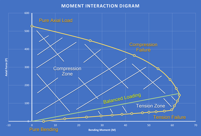
Nowością w programie RFEM 6 podczas wymiarowania słupów betonowych jest możliwość generowania wykresu interakcji momentów zgodnie z ACI 318-19 [1]. Podczas wymiarowania prętów żelbetowych istotnym narzędziem jest wykres interakcji momentów. Wykres interakcji momentów przedstawia zależność między momentem zginającym a siłą osiową w dowolnym punkcie zbrojenia. Cenne informacje, takie jak wytrzymałość i zachowanie betonu w różnych warunkach obciążenia, wyświetlane są wizualnie.
Metoda CSA S16:19 Skutki stateczności w analizie sprężystej w Załączniku O.2 stanowi alternatywę dla metody Uproszczonej analizy stateczności z punktu 8.4.3. W tym artykule zostaną opisane wymagania załącznika O.2 i zastosowania w RFEM 6.
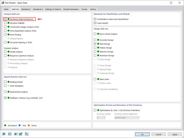
Rozszerzenie Nieliniowe zachowanie materiału umożliwia uwzględnienie nieliniowości materiałowych w programie RFEM 6. Ten artykuł zawiera przegląd dostępnych nieliniowych modeli materiałowych, które są dostępne po aktywowaniu tego rozszerzenia w danych bazowych modelu.
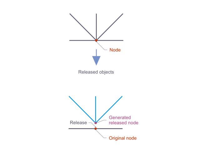
Zwolnienia węzłowe są to specjalne obiekty w programie RFEM 6, które umożliwiają konstrukcyjne odłączenie obiektów dołączonych do węzła. Zwolnienie jest sterowane przez warunki typu zwolnienia, które również mogą mieć właściwości nieliniowe. W tym artykule przedstawiono definicję zwolnień węzłowych na praktycznym przykładzie.

Osłony przeciwwiatrowe to specjalne konstrukcje tekstylne, które mają za zadanie chronić środowisko przed szkodliwymi cząsteczkami chemicznymi, jak również ograniczać erozję wietrzną, przyczyniając się do ochrony cennych zasobów. RFEM i RWIND są używane do analizy konstrukcji wiatrowej dla jednostronnej interakcji płyn-konstrukcja (FSI).
W tym artykule pokazano, jak wymiarować osłony przeciwwiatrowe przy użyciu programów RFEM i RWIND.
W tym artykule pokazano, jak wymiarować osłony przeciwwiatrowe przy użyciu programów RFEM i RWIND.
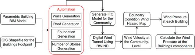
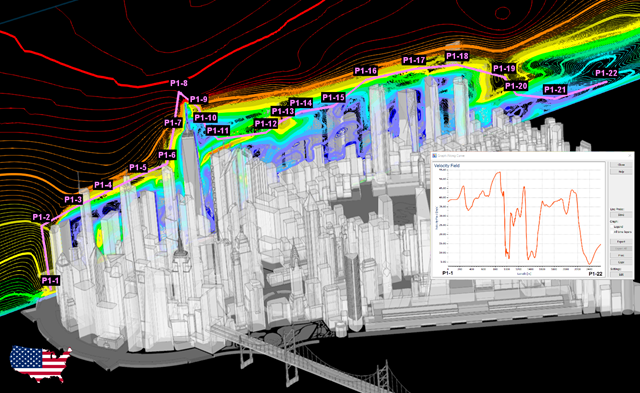
W artykule tym opracowano nowatorskie podejście do generowania modeli CFD na poziomie miejscowości poprzez połączenie modelowania informacji o budynku (BIM) i systemów informacji geograficznej (GIS) w celu zautomatyzowania generowania trójwymiarowego modelu terenu o wysokiej rozdzielczości, który zostanie wykorzystany jako dane wejściowe dla cyfrowego tunelu aerodynamicznego z wykorzystaniem RWIND.
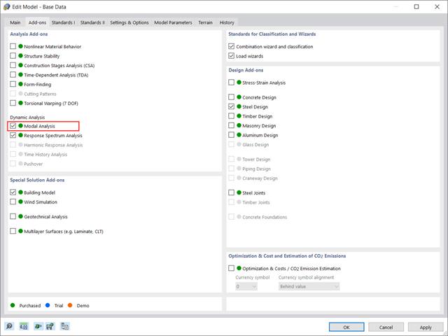
Rozszerzenie „Analiza modalna” w RFEM 6 umożliwia przeprowadzanie analizy modalnej układów konstrukcyjnych, określając w ten sposób wartości drgań własnych, takie jak częstotliwości drgań własnych, kształty modalne, masy modalne i efektywne modalne współczynniki masy. Wyniki te można wykorzystać do obliczeń drgań, a także do dalszych analiz dynamicznych (na przykład obciążenia widmem odpowiedzi).
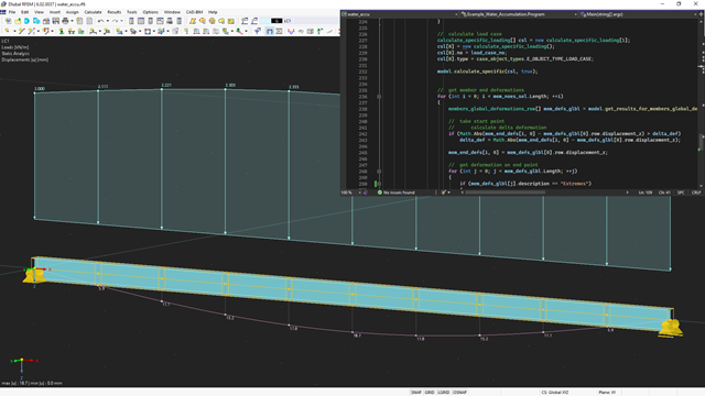
API dla RFEM 6, RSTAB 9 i RSECTION opiera się na koncepcji usług sieciowych (Webservice). Aby zapoznać się z tematem, w poniższym artykule omawiamy kolejny przykład w języku C#.
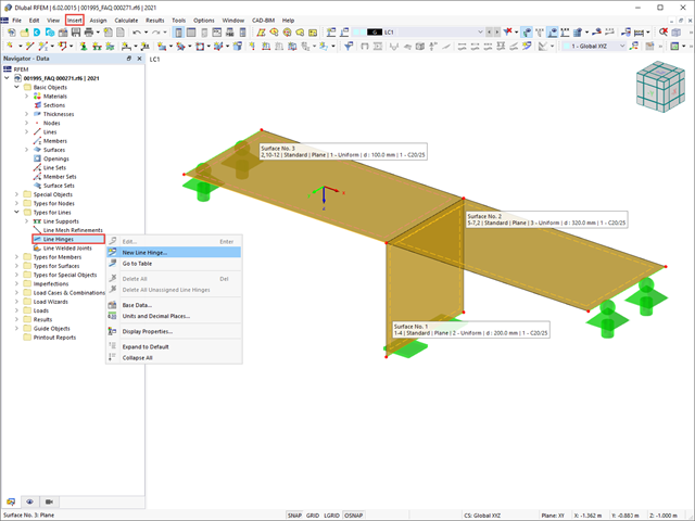
W tym artykule pokażemy, jak prawidłowo uwzględnić połączenie między powierzchniami stykającymi się na jednej linii za pomocą przegubów liniowych w programie RFEM 6.
W tym artykule podsumowano zalety pracy ze sparametryzowanymi modelami w programach RFEM 6 i RSTAB 9.
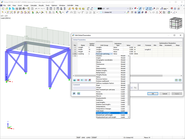
Z tego artykułu dowiesz się, jak zoptymalizować parametry globalne w programie RFEM 6 w zależności od różnych aspektów.
Samodzielny program RSECTION określa właściwości przekrojów cienkościennych i masywnych oraz przeprowadza analizę naprężeń. W poprzednim artykule z Bazy wiedzy zatytułowanym "Graficzne/tabelaryczne tworzenie przekrojów zdefiniowanych przez użytkownika w PRZEKRÓJ 1" omówiono podstawy definiowania przekrojów w programie. Z drugiej strony, ten artykuł jest podsumowaniem sposobu określania właściwości przekroju i przeprowadzania analizy naprężeń.

Dzięki rozszerzeniu Połączenia stalowe dla RFEM 6 można tworzyć i analizować połączenia stalowe przy użyciu wydzielonego modelu ES. Modelowanie połączeń można kontrolować poprzez proste i wygodne wprowadzanie elementów. Elementy stalowego połączenia można definiować ręcznie lub przy użyciu szablonów dostępnych w bibliotece. Pierwsza metoda została opisana w poprzednim artykule z Bazy wiedzy zatytułowanym „Nowe podejście do wymiarowania połączeń stalowych w programie RFEM 6”. W tym artykule skupimy się na tej drugiej metodzie; tzn. pokaże, jak definiować komponenty połączenia stalowego przy użyciu szablonów dostępnych w bibliotece programu.
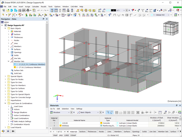
Aby przeprowadzić analizę ugięcia we właściwy sposób, ważne jest, aby "informować" program o dokładnych warunkach podparcia elementu będącego przedmiotem zainteresowania. Definicja podpór obliczeniowych w programie RFEM 6 zostanie wyświetlona dla zbioru prętów żelbetowych.
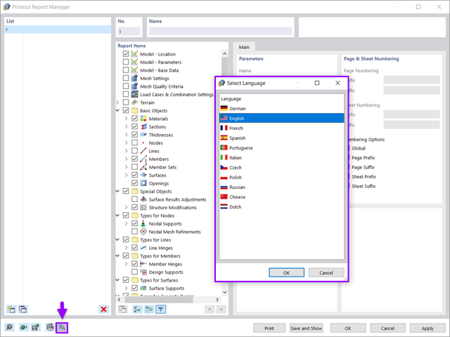
Wszystkie dane w programie RFEM 6 można udokumentować w wielojęzycznym raporcie. Protokół wydruku jest nowoczesny i zoptymalizowany w porównaniu z poprzednią generacją programu (RFEM 5). W tym artykule technicznym przedstawiono niektóre z najważniejszych funkcji.

W tym artykule opisano, w jaki sposób płaska płyta budynku mieszkalnego jest modelowana w programie RFEM 6 i wymiarowana zgodnie z Eurokodem 2. Płyta ma grubość 24 cm i jest podparta na słupach o długości 45/45/300 cm w rozstawie co 6,75 m (rysunek 1). Słupy są modelowane jako sprężyste podpory węzłowe poprzez zdefiniowanie sztywności sprężystej na podstawie warunków brzegowych (rysunek 2). Jako materiały wybrano beton C35/45 i stal zbrojeniową B 500 S (A).
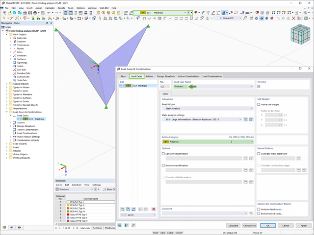
Program RFEM 6 zawiera rozszerzenie Form-Finding do określania kształtów równowagi modeli powierzchni obciążonych rozciąganiem i prętów obciążonych siłami osiowymi. Aktywuj ten dodatek w Danych bazowych modelu i użyj go, aby znaleźć położenie geometryczne, w którym naprężenie wstępne lekkich konstrukcji jest w równowadze z istniejącymi warunkami brzegowymi.
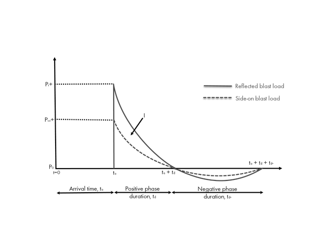
Obciążenia eksplozją od materiałów wybuchowych o dużej energii, przypadkowe lub celowe, są rzadkie, ale mogą być wymogiem projektowym. Obciążenia dynamiczne tego typu różnią się od normalnych obciążeń statycznych – są to obciążenia o znacznej wartości, ale oddziałujące bardzo krótkotrwale. Scenariusz eksplozji można przeprowadzić bezpośrednio w programie MES jako analizę historii czasowej, aby zminimalizować utratę żywotności i ocenić różne poziomy uszkodzeń konstrukcji.
W artykule omówiono elementy, w odniesieniu do których przekrój jest poddany jednocześnie działaniu momentu zginającego, siły tnącej oraz osiowej siły ściskającej lub rozciągającej. W naszym przykładzie nie uwzględnimy jednak obciążenia siłą tnącą.
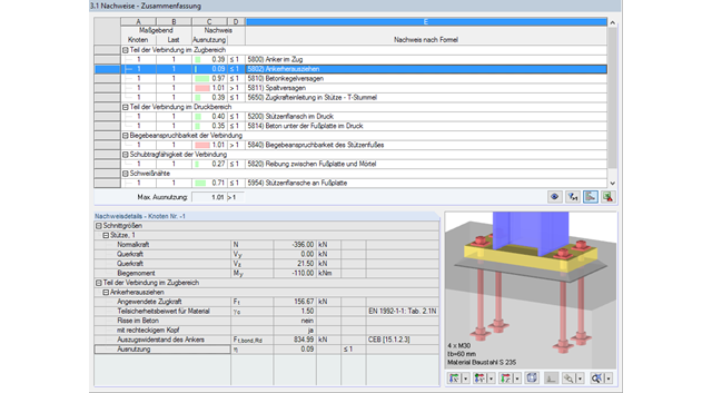
Rodzina produktów Dlubal Software obejmuje różne moduły do wymiarowania połączeń stalowych i drewnianych. So besteht im Modul RF-/JOINTS Stahl Stützenfuß die Möglichkeit, Fußpunkte von gelenkigen oder eingespannten Stahlstützen zu untersuchen. Für die wirtschaftliche und sichere Bemessung des Stützenfußes spielt die Auswahl der Befestigungsmittel, der Fundamentgeometrie und der Materialgüten eine entscheidende Rolle.
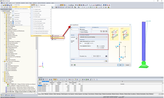
In the AISC 360 – 14th Ed. C2.2, the direct analysis method requires initial imperfections to be taken into consideration. The important imperfection of recognition is column out-of-plumbness. According to C2.2a, the direct modeling of imperfections is one method to account for the effect of initial imperfections. However, in many situations, the expected displacements may not be known or easily predicted.