122 Wyniki
Wyświetl wyniki:
Sortuj według:

Niniejszy artykuł dotyczy długotrwałego ugięcia konstrukcji betonowych zgodnie z ACI 318 i CSA A23.3.

Podczas obliczania siły tnącej w programie Wymiarowanie betonu zbrojonego, działającą siłę tnącą Vz można zredukować zgodnie z EN 1992-1-1. Poniższy artykuł opisuje redukcję siły tnącej od obciążeń skupionych w pobliżu podpory oraz wymiarowanie sił tnących w odległości d od krawędzi podpory w przypadku obciążenia równomiernie rozłożonego.

Dzięki rozszerzeniu Projektowanie konstrukcji stalowych możliwe jest projektowanie konstrukcji stalowych zgodnie z normą AISC 360-22. W poniższym artykule porównano wyniki obliczeń zwichrzenia zgodnie z rozdziałem F z analizą wartości własnych.
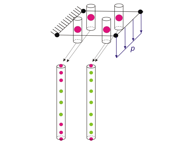
![Podstawowe kształty konstrukcji membranowych [1]](/pl/webimage/009595/2419506/01-png.png?mw=640&hash=8a9ac87bf3acfb73e6cad970f55eb968a841595c)
Niniejszy artykuł skupia się na specyficznych aspektach projektowania konstrukcji membranowych, które mają specyficzne wymagania, takich jak znajdowanie kształtu (form-finding) i generowanie szablonów cięcia. Integralną częścią projektowania tych konstrukcji jest proces wyszukiwania odpowiednich wstępnie sprężonych kształtów i generowania szablonów cięcia. Tekst krótko opisuje dwa podstawowe procesy w projektowaniu konstrukcji membranowych. Celem jest zilustrowanie ich fizycznego charakteru i zademonstrowanie poszczególnych stwierdzeń za pomocą towarzyszących im przykładów.
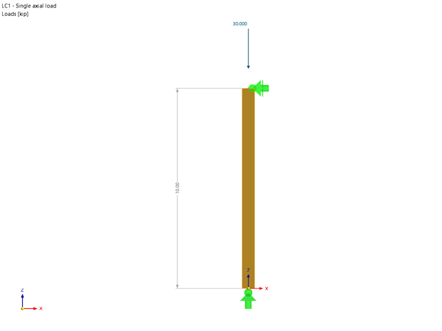
Rozszerzenie Wymiarowanie drewna umożliwia wymiarowanie słupów drewnianych zgodnie ze standardową metodą ASD 2018 NDS. Dokładne wyznaczenie nośności na ściskanie oraz współczynników redukcyjnych dla prętów drewnianych jest konieczne dla bezpieczeństwa konstrukcji. Poniższy artykuł weryfikuje maksymalną wytrzymałość na wyboczenie krytyczną obliczoną w module rozszerzeniowym Wymiarowanie drewna przy użyciu równań analitycznych krok po kroku zgodnie z normą NDS 2018, w tym współczynników dostosowania przy ściskaniu, skorygowanej wartości obliczeniowej na ściskanie i końcowego stopnia wyboczenia.

Obliczenia ze względu na zmęczenie zgodnie z EN 1992-1-1 należy przeprowadzać w przypadku elementów konstrukcyjnych, które są poddane działaniu dużych zakresów naprężeń i/lub wielu zmianom obciążenia. W takim przypadku obliczenia dla betonu i zbrojenia są przeprowadzane osobno. Dostępne są dwie alternatywne metody obliczeniowe.

Obliczanie ramy momentowej zgodnie z AISC 341-16 jest teraz możliwe w rozszerzeniu Projektowanie konstrukcji stalowych dla programu RFEM 6. Wynik obliczeń sejsmicznych jest podzielony na dwie sekcje: wymagania dotyczące prętów i połączeń. W tym artykule omówiono wymaganą wytrzymałość połączenia. Przedstawiono przykładowe porównanie wyników pomiędzy RFEM a AISC Seismic Design Manual.

W tym artykule opisano na przykładzie płyty z betonu włóknistego, które wpływają na zastosowanie różnych metod całkowania i różnej liczby punktów całkowania na wynik obliczeń.
![Rozpiętości na podstawie Rysunku 5.2 z [1]](/pl/webimage/039540/3493372/01_Abmessungen_EN.png?mw=640&hash=a3c436931baff3514db261b2d11bfa39abae9170)
Aby poprawnie zwymiarować dźwigar lub belkę teową w programie RFEM 6 i w module dodatkowym 'Wymiarowanie betonu', ważne jest określenie 'szerokości pasów' prętów żebrowych. W tym artykule omówiono opcje wprowadzania danych dla belki dwuprzęsłowej oraz obliczanie wymiarów pasów zgodnie z EN 1992-1-1.
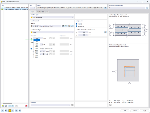
Automatyczny proces wymiarowania zbrojenia określa zbrojenie powierzchniowe, które zapewnia wymaganą ilość zbrojenia wynikającego z obliczeń.
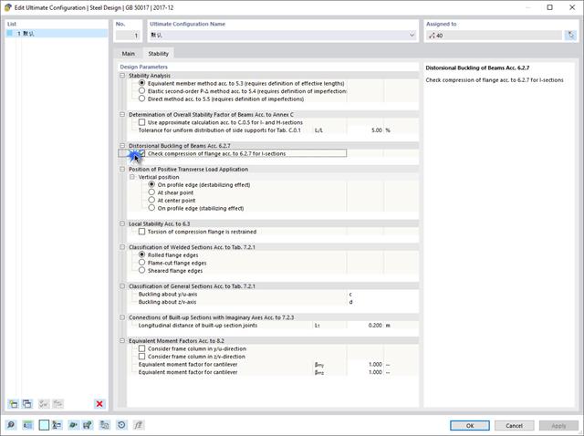
Jeżeli na górnej półce znajduje się płyta betonowa, działa ona jak podpora boczna (konstrukcja zespolona) i zapobiega problemom ze statecznością przy wyboczeniu skrętnym. Jeżeli moment zginający jest ujemny, dolna półka jest obciążona, a górna rozciągana. Jeżeli podparcie boczne nie jest wystarczające ze względu na sztywność środnika, kąt pomiędzy dolną półką a linią nacięcia środnika jest zmienny, przez co istnieje możliwość wystąpienia niestateczności wymiarowej dolnej półki.
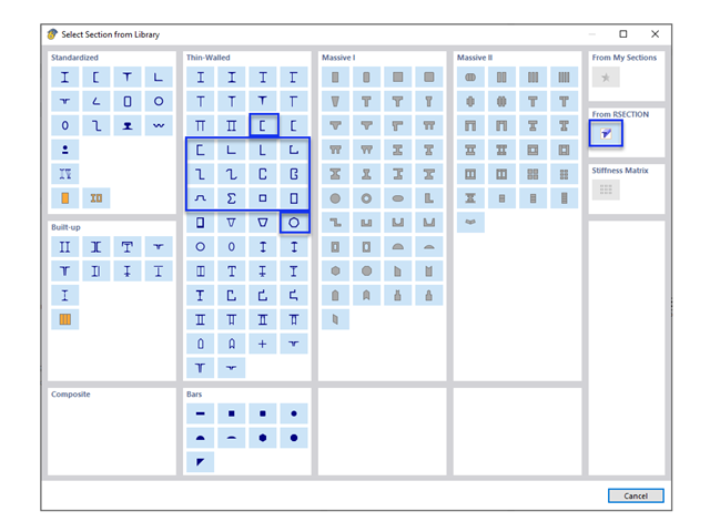
W obliczeniach konstrukcji stalowych formowanych na zimno często wymagane są niestandardowe przekroje. In RFEM 6, the custom section can be created using one of the “Thin-Walled” sections available in the library. For other sections that do not meet any of the 14 available cold-formed shapes, the sections can be created and imported from the standalone program, RSECTION. For general information on AISI steel design in RFEM 6, refer to the Knowledge Base article provided at the end of the page.
Jak już zapewne wiesz, w programie RFEM 6 istnieje możliwość uwzględnienia nieliniowości materiałowych. W tym artykule wyjaśniono, jak określać siły wewnętrzne w płytach modelowanych z użyciem materiału nieliniowego.
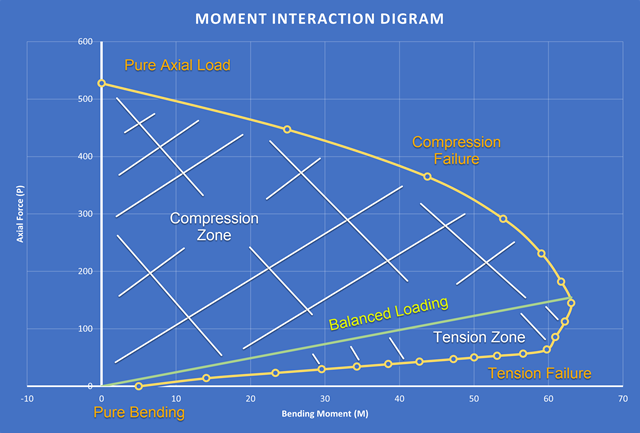
Nowością w programie RFEM 6 podczas wymiarowania słupów betonowych jest możliwość generowania wykresu interakcji momentów zgodnie z ACI 318-19 [1]. Podczas wymiarowania prętów żelbetowych istotnym narzędziem jest wykres interakcji momentów. Wykres interakcji momentów przedstawia zależność między momentem zginającym a siłą osiową w dowolnym punkcie zbrojenia. Cenne informacje, takie jak wytrzymałość i zachowanie betonu w różnych warunkach obciążenia, wyświetlane są wizualnie.

Wymiarowanie prętów stalowych formowanych na zimno zgodnie z AISI S100-16 jest teraz dostępne w programie RFEM 6. Design can be accessed by selecting “AISC 360” as the standard in the Steel Design add-on. “AISI S100” is then automatically selected for the cold-formed design (Image 01).
,_Table_22.5.5.1_ACI_318-19.png?mw=640&hash=7e50d54e01238943fe1c691c0aa197d9b2fa8511)
W najnowszej normie ACI 318-19 długoterminowa zależność w określaniu nośności betonu na ścinanieVc zostaje przedefiniowana. Dzięki nowej metodzie wysokość pręta, stopień zbrojenia podłużnego i naprężenie normalne wpływają teraz na wytrzymałość na ścinanie Vc. W poniższym artykule opisano zaktualizowane podejście do obliczeń dla ścinania, a zastosowanie przedstawiono na przykładzie.
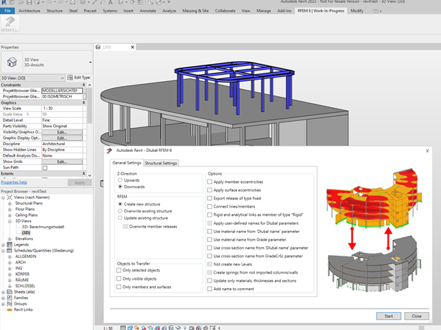
Podobnie jak w przypadku poprzednich generacji programów firmy Dlubal, zintegrowany interfejs z Autodesk Revit jest teraz dostępny dla programów RFEM 6 i RSTAB 9. W tym artykule przedstawiono ogólne informacje na temat interfejsu oraz obiektów konstrukcyjnych i parametrów związanych z firmą Dlubal w programie Revit.

Niniejszy artykuł jest związany z trwającym projektem, w ramach którego opracowywany i wdrażany jest cyfrowy bliźniak konstrukcyjny mostu Kalix w Szwecji.
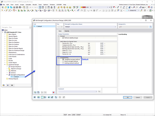
W tym artykule omówiono dostępne opcje określania nominalnej wytrzymałości na zginanie Mnlb dla stanu granicznego wyboczenia lokalnego, podczas projektowania zgodnie z Aluminium Design Manual (Podręcznik projektowania konstrukcji aluminiowych 2020).
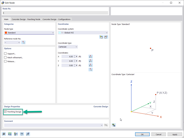
Optymalnym scenariuszem, w którym należy zastosować obliczenia wytrzymałości na przebicie, zgodnie z ACI 318-19 lub CSA A23.3:19, jest sytuacja, w której w płycie występuje duża koncentracja obciążeń lub sił reakcji występujących w jednym węźle. W programie RFEM 6 węzeł, w którym występuje przebicie, nazywany jest węzłem z przebiciem. Przyczyny tak dużej koncentracji sił mogą być spowodowane przez słup, siłę skupioną lub podporę węzłową. Łączenie ścian może również powodować obciążenia skupione na końcach, narożach i na końcach obciążeń liniowych i podpór.
Konstrukcje murowe można modelować i analizować w programie RFEM 6 za pomocą rozszerzenia Projektowanie konstrukcji murowych, który wykorzystuje do obliczeń metodę elementów skończonych. Zakładając, że w programie zaimplementowano nieliniowy model materiałowy, można modelować złożone konstrukcje murowe oraz przeprowadzać analizę statyczną i dynamiczną, aby przedstawić nośność konstrukcji murowej oraz różne mechanizmy uszkodzenia. Istnieje możliwość wprowadzania i modelowania konstrukcji murowych bezpośrednio w programie RFEM 6 oraz łączenia modelu materiałowego muru ze wszystkimi popularnymi rozszerzeniami dla programu RFEM. Umożliwia to projektowanie całych modeli budynków w połączeniu z murem.

Rozszerzenie Wymiarowanie betonu umożliwia wymiarowanie słupów betonowych zgodnie z ACI 318-19. Poniższy artykuł potwierdzi wymiarowanie zbrojenia w rozszerzeniu Wymiarowanie betonu przy użyciu równań analitycznych krok po kroku zgodnie z normą ACI 318-19, w tym wymagane zbrojenie podłużne, pole przekroju brutto i rozmiar/rozstaw ściągu.
Zgodnie z rozdz. 6.6.3.1.1 i 10.14.1.2 ACI 318-19 i CSA A23.3-19, program RFEM efektywnie uwzględnia redukcję sztywności prętów betonowych i powierzchni dla różnych typów elementów. Dostępne typy wyboru obejmują zarysowane i niezarysowane ściany, płaskie płyty, belki i słupy. Dostępne w programie mnożniki zaczerpnięto bezpośrednio z tabel 6.6.3.1.1(a) i 10.14.1.2.
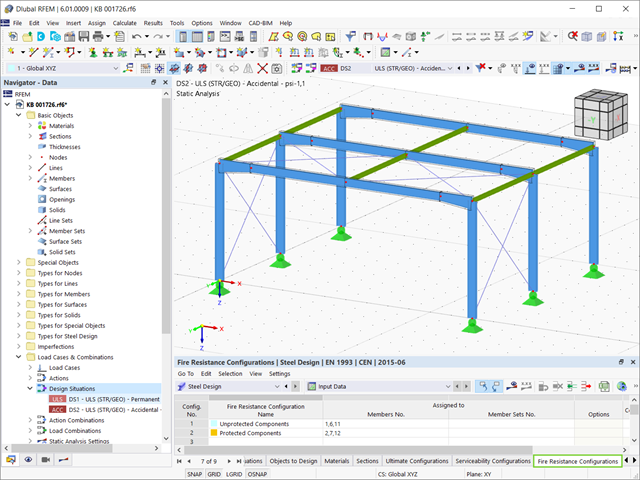
Stal ma słabe właściwości termiczne pod względem ognioodporności. Rozszerzalność termiczna dla wzrastającej temperatury jest bardzo duża w porównaniu z rozszerzalnością innych materiałów budowlanych i może powodować efekty, których nie byłoby w obliczeniach w normalnej temperaturze ze względu na utwierdzenie elementu. Wraz ze wzrostem temperatury wzrasta ciągliwość stali, a jej wytrzymałość maleje. Ponieważ stal traci 50% swojej wytrzymałości w temperaturze 600 °C, ważne jest, aby chronić elementy przed skutkami pożaru. W przypadku zabezpieczonych elementów stalowych, dzięki lepszej reakcji termicznej można wydłużyć ognioodporność.

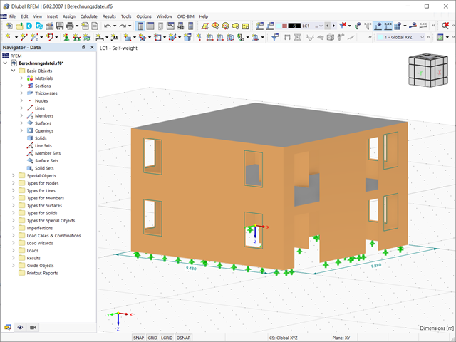
W tym artykule opisano, w jaki sposób płaska płyta budynku mieszkalnego jest modelowana w programie RFEM 6 i wymiarowana zgodnie z Eurokodem 2. Płyta ma grubość 24 cm i jest podparta na słupach o długości 45/45/300 cm w rozstawie co 6,75 m (rysunek 1). Słupy są modelowane jako sprężyste podpory węzłowe poprzez zdefiniowanie sztywności sprężystej na podstawie warunków brzegowych (rysunek 2). Jako materiały wybrano beton C35/45 i stal zbrojeniową B 500 S (A).
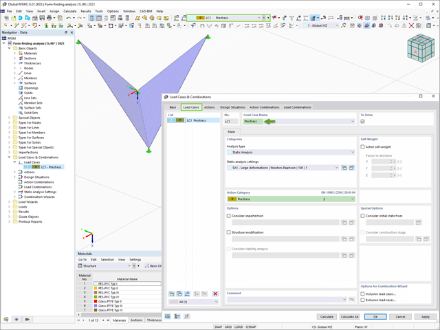
Program RFEM 6 zawiera rozszerzenie Form-Finding do określania kształtów równowagi modeli powierzchni obciążonych rozciąganiem i prętów obciążonych siłami osiowymi. Aktywuj ten dodatek w Danych bazowych modelu i użyj go, aby znaleźć położenie geometryczne, w którym naprężenie wstępne lekkich konstrukcji jest w równowadze z istniejącymi warunkami brzegowymi.
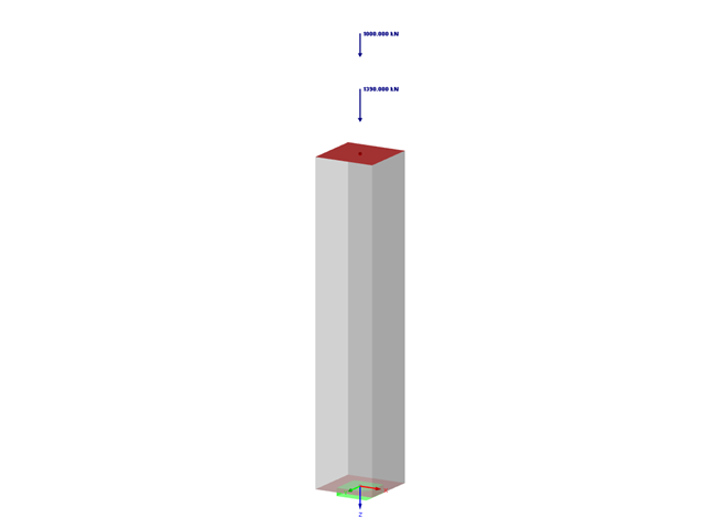
W artykule omówiono elementy prostoliniowe, których przekrój poprzeczny poddany jest osiowej sile ściskającej. Celem tego artykułu jest pokazanie, ile parametrów dotyczących obliczeń słupów betonowych zdefiniowanych w Eurokodach jest uwzględnianych w programie do analizy statyczno-wytrzymałościowej RFEM 5.

W tym artykule porównujemy obliczenia z obliczeniami w artykule odniesieniem: Wymiarowanie słupów betonowych poddanych ściskaniu osiowemu w RF-CONCRETE Members. Dlatego chodzi o odtworzenie dokładnie tego samego zastosowania teoretycznego, które zostało przeprowadzone w RF-CONCRETE Members, i odtworzenie go w RF-CONCRETE Columns. Celem jest porównanie różnych parametrów wejściowych i wyników uzyskanych za pomocą dwóch modułów dodatkowych do wymiarowania słupowych prętów betonowych.
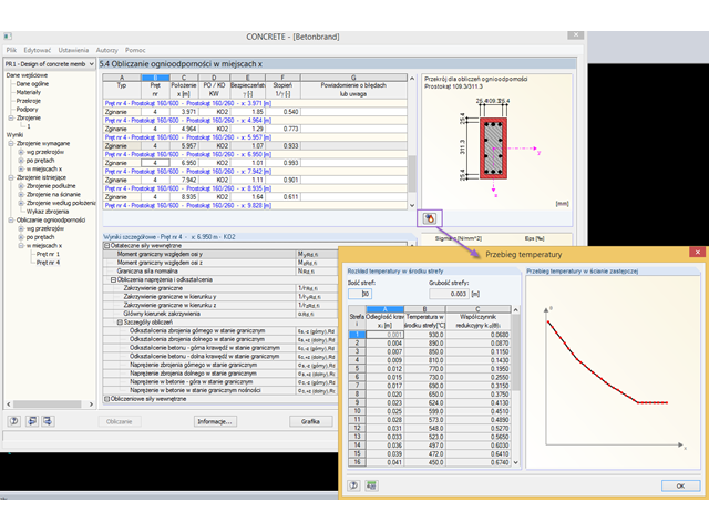
Wymiarowanie betonu zbrojonego na wypadek pożaru przeprowadza się zgodnie z metodą uproszczoną opartą na normie EN 1992-1-2, rozdz. 4.2. Dabei wird die im Anhang B.2 beschriebene "Zonenmethode" benutzt: Der Querschnitt wird in eine Anzahl paralleler Zonen gleicher Dicke unterteilt und deren temperaturabhängige Druckfestigkeit ermittelt. Die reduzierte Tragfähigkeit bei Brandeinwirkung wird so durch einen verkleinerten Bauteilquerschnitt mit abgeminderten Festigkeiten abgebildet.
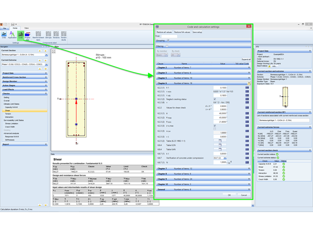
In RF-TENDON und RF-TENDON Design können Einstellungen zu normenabhängigen Beiwerten, Berechnungsparametern und Berechnungsverfahren über die Funktion "Norm" eingesehen und angepasst werden. In dem Dialog können die Einstellungs- und Anpassungsmöglichkeiten nach Kapitel der Norm gruppiert angezeigt werden.