


The building layout is designed to provide full flexibility due to the fact that there are no columns in the production areas.
Consistent with Industry 4.0’s approach, the planning process is also digitized - this is specifically implemented in the structural analysis and the creation of all necessary plans and planning documents.
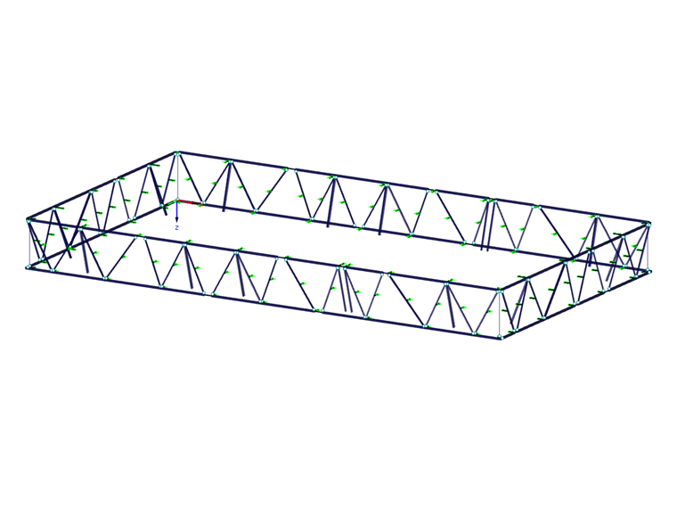
The building consists of a basement with an underground parking garage, a high-ceilinged first floor without columns, and three upper floors. The two top floors are cantilevered in all directions from the building sides and are placed on trusses bordering all four sides of the structure. These truss structures span the full height of the two upper floors and are supported on individual inclined columns.
The ceiling loads are transferred via the facade trusses to the diagonal columns arranged on the longitudinal and transverse sides. Further load transfer takes place via the columns in the building structure, utilizing reinforced concrete cores and steel trusses. The transfer of vertical loads from the upper chord of the truss via the nodal section into the inclined column results in horizontal deflection forces at the column head. These forces are transferred into the reinforced concrete ceiling via the ceiling plate. The upper and lower stories are supported on the facade trusses’ upper and lower chords. The middle story sits on the truss diagonals via steel brackets, which are therefore subjected not only to axial forces, but also to bending. Even though this is an uncommon loading in a truss, the axial load clearly governs in comparison with the bending behavior.
This truss structure is unique because it is located outside the insulated building envelope and is exposed to climatic temperature changes. The steel structure is designed for temperature changes of -22°F to 86°F. This results in normal forces of up to approximately 900 kips with alternating loading in the upper and lower chords. The support brackets must therefore not only allow the transfer of vertical loads from the reinforced concrete slabs, but also ensure the transfer of horizontal restraint forces from temperature differences into the reinforced concrete slabs.
The facade trusses’ upper and lower chords consist of hot-rolled square tube sections, 16x16x0.79 in. Greater wall thicknesses (up to 1.18 inches) are required in the joint areas to absorb the nodal stresses. In order to construct this complex joint geometry, they are welded together from individual plates. The diagonals are designed as classic HEA, HEB, or HEM sections, depending on the load. The connections to the upper and lower chords are attained by welded stubs in the joint area. The diagonal member is then connected with a bolted end plate joint.
| Location | Schorenweg 4144 Arlesheim, Switzerland
|
| Owner | uptownBasel AG Arlesheim, Switzerland uptownbasel.ch |
| Architecture | Fankhauser Architektur AG Reinach, Switzerland www.f-web.ch |
| Structural Design | Gruner AG Basel, Switzerland www.gruner.ch |


