


This article presents an example of cross-section checks of a column set in a concrete bucket foundation. This example is also described in [1].
Structural System
The column is a cross-section HEB 280 made of steel S 235 JR.
![System and Loading According to [1]](/en/webimage/009634/2419765/01-en-png-png.png)
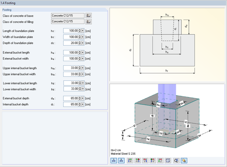
Geometry parameters of the column base are set in Window 1.4 of RF-/JOINTS in compliance with [1]. The selected restraining depth is 65 cm.
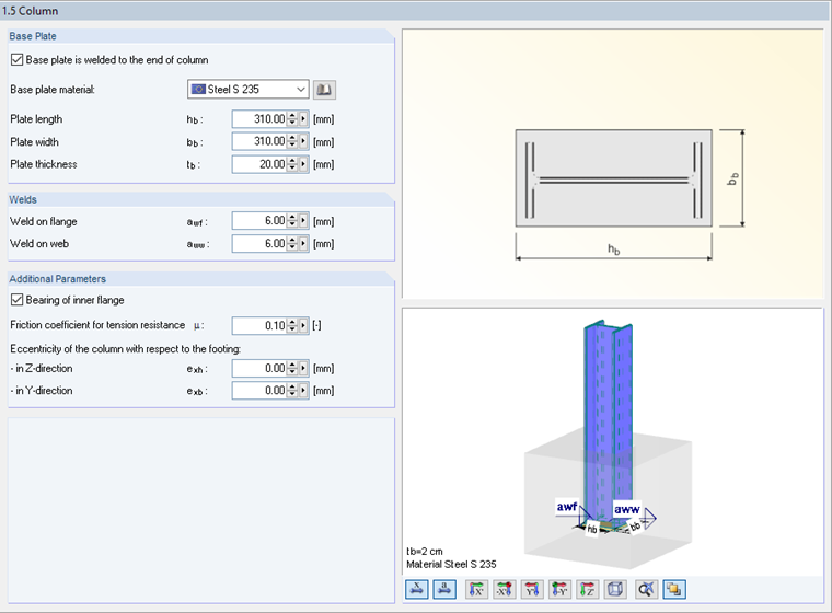
The parameters of the base plate are defined in Window 1.5.
Internal Forces
The following design internal forces are available.
NEd = 396.0 kN
VEd = 21.5 kN
MEd = -118.0 kN
Design of Required Bucket Depth
The governing value is the minimum restraining depth based on the concrete strength.
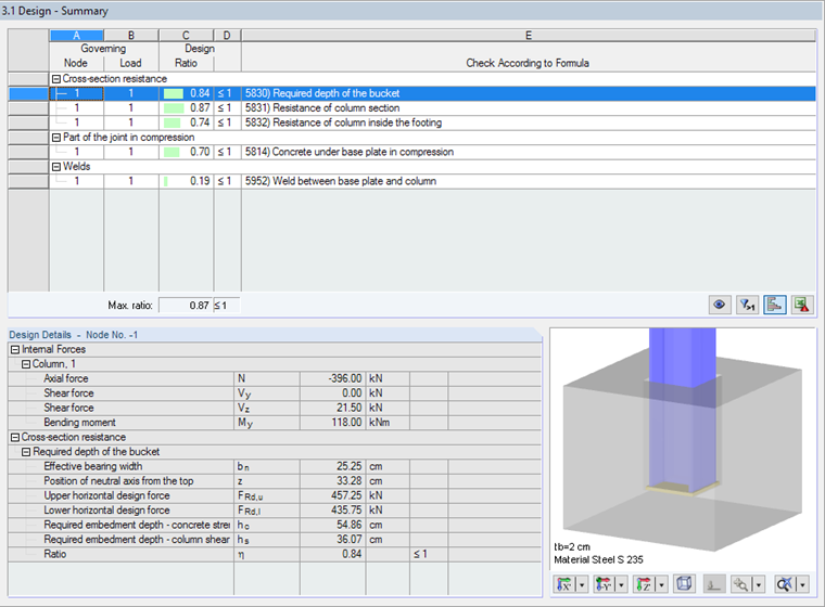
The minimum restraining depth of 54.86 cm is required. This is provided by the selected depth of 65 cm.
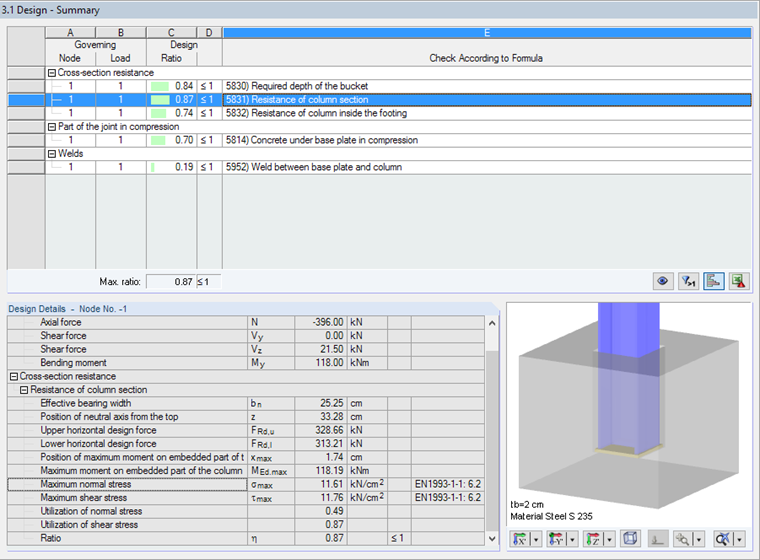
Design of Column Section Resistance
The force and moment distribution in the column corresponds to the following distribution, according to [1].
![Distribution of Forces and Moments in Column Base According to [1]](/en/webimage/009638/2419805/05-en-png-png.png)
Normal stress from the maximum moment is calculated as follows:
For the maximum shear stress, the following applies:
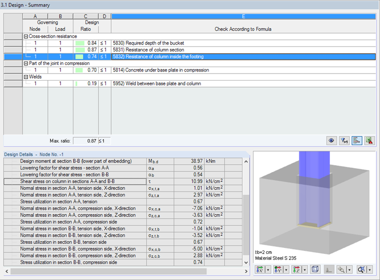
The corresponding stresses and design details can also be found in the result table under Cross-section resistance.
Design of Column Inside Bucket
Image 05 shows the design-relevant locations. Governing is the section B-B on the compression side (location b in Image 05):
The normal stress in the X-direction is calculated as follows:
The following normal stress acts in the Z-direction:
For the maximum shear stress, the following applies:
Design Details of Window 3.1 include the corresponding stresses and ratios:
The program completes the design by analyzing the joint in compression and the welds. However, these are not explained in this article.
Conclusion
RF-/JOINTS Steel – Column Base allows you to design footings of hinged and restrained column bases. In the case of a column set in a concrete bucket, the add-on module analyzes the required depth of the bucket, the resistance of the column section, and the resistance of the column inside the footing with regard to the arising tension and compression stresses. The analysis is completed by the design of the concrete under the base plate in compression as well as the design of welds between the base plate and the column.