


Basic settings for Aluminum Design are managed in the “Global Settings” dialog box. This chapter describes the settings available in the dialog box. These settings are independent of the design standard, but the default values may differ from one another.

Accessing Global Settings
You can access the global settings in one of the following ways:
- Shortcut menu in the “Aluminum Design” navigator entry
- Button
 in the toolbar of the Aluminum Design tables.
Clicking the
![]() button restores the default settings of the dialog box according to the selected design standard.
button restores the default settings of the dialog box according to the selected design standard.
Configurations to Calculate
The design is preset in all available configurations. However, if you do not want to perform serviceability limit state design, for example, you can deactivate the serviceability configuration here. Thus, no serviceability limit state design checks are carried out and the input data for the aluminum design is reduced accordingly. Design situations that are assigned to a deactivated configuration are no longer taken into account in the design. A design situation can be assigned in the Design Situations table.
Smoothing Settings
The smoothing settings are relevant for the design of surfaces. The stresses are determined for the nodes of the FE mesh and then smoothed using an interpolation method. This allows you to see a continuous distribution of the results in the graphic.
You can select from the following smoothing settings in the list:
- Constant in mesh elements
- Not continuous
- Continuous within surfaces
- Continuous within surface sets, otherwise within surfaces (default setting)
- Continuous within all surfaces
The individual options are described in the chapter Result Smoothing of the RFEM manual.
Analysis Method
In this section, you can control how the internal forces of the load and result combinations are transferred to the design. The list contain three analysis methods you can select from:
- Enumeration Method
All load and result combinations included in a design situation are calculated individually. This approach usually leads to the most accurate results, but may also lead to increased calculation time.
- Envelope Method
First, the enveloping internal forces (max/min) of all load and result combinations included in a design situation are calculated. The design checks are then performed using these internal forces. Compared to the Enumeration Method, this usually results in a shorter calculation time. However, it cannot be ruled out that all constellations are covered.
- Mixed Method
This approach provides a compromise between the other two methods: You can specify an upper limit for the variants of a design situation for the members and surfaces, which are then designed using the enumeration method. As soon as the number of load and result combinations exceeds this limit, the design is performed using the envelope method.
Check of Member / Member Set Slendernesses
As part of the aluminum design, you can also check the slenderness of members and member sets subjected to tension, compression, or bending. The limit values to be checked are specified here. If effective lengths are defined for the members or member sets to be designed, they are taken into account when calculating the slenderness. The evaluation is carried out in the result tables for slenderness.
Optimization – Maximum Allowable Design Ratio
In the add-on, you can perform an optimization for standardized cross-sections (see also the section Cross-Sections). When checking the possible variants, the utilization of the variant is compared with the maximum value defined here.
Storing Results
For models with several thousand objects, the result files can become very large. The list contains two options that you can select to influence how the design results are saved.
- By location or By mesh node / grid point
The maximum results are saved for all stress points of the members or FE mesh nodes and grid points of the surfaces. This has a corresponding effect on the file size.
- By object
Only the maximum results for each member or surface are saved. The result file is significantly smaller.
Smoothing Settings for Result Beam Calculation
A result beam integrates the internal forces of members, surfaces, or solids. For the design in the add-on, you can control which smoothing setting is applied when integrating the results. The following options are available in the list:
- Constant in mesh elements
- Not continuous
- Continuous within surfaces or solids
- Continuous within surface sets or solid sets, otherwise within surfaces or solids
- Continuous within all surfaces or solids
The individual options are described in the chapter Result Smoothing of the RFEM manual.
Display Results
If the “Display Results by Design Situation” check box is selected, the results are displayed separately in the tables for each design situation.
Calculate Results
The results of the surfaces are based on the results in the FE mesh nodes, which are prepared for graphical output taking into account the smoothing settings. As for the results of the structural analysis, you can select in the Navigator – Results whether the values are displayed in the FE mesh nodes or in the grid points of the surfaces (see the chapter grid-mesh Result Values on Surfaces of the RFEM manual).
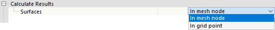
The two options in the list refer to the results in the tables: You can use them to control whether the values of the mesh nodes or the grid points are output. The grid of the surfaces represents an output independent of the FE mesh in result points with regular intervals (see the chapter Surfaces of the RFEM manual).
Settings for Sections
Some design standards contain sections that only apply to closed or open cross-sections. The distinction between open and closed cross-sections for general cross-section shapes is made by considering the Bredt component It,Bredt of the total torsional moment of inertia It. For closed cross-sections, the torsional moment of inertia is almost entirely determined by the Bredt component.
Life Cycle of Results
Once you make a change to the input data, the Aluminum Design results are deleted. This ensures that the design is based on the correct boundary conditions. In some cases, however, it may be useful to retain the results (for example, to make a change in a complex model that does not affect the design). In this case, deactivate the check box. No recalculation will be performed when a change is made. All results affected by this change will then be displayed in red. They may no longer be valid. They will only be updated after a recalculation.