36 Results
View Results:
Sort by:

In order to be able to carry out a pushover analysis, it is necessary to transform the determined capacity curve into a simplified form. The N2 method is described in Eurocode EN 1998. This article should help to explain what a bilinearization according to the N2 method involves.

The automatic surface reinforcement design process determines a surface reinforcement that covers the required amount of reinforcement.

- 001819
- Design
- Aluminum Design for RFEM 6
-
- Aluminum Design for RSTAB 9
- Concrete Design for RFEM 6
- Concrete Design for RSTAB 9
- Steel Design for RFEM 6
- Steel Design for RSTAB 9
- Timber Design for RFEM 6
- Timber Design for RSTAB 9
- Concrete Structures
- Steel Structures
- Timber Structures
- Structural Analysis & Design
- Eurocode 0
- Eurocode 2
- Eurocode 3
- Eurocode 5
- Eurocode 9
- ADM
- ANSI/AISC 360
For the serviceability of a structure, the deformations must not exceed certain limit values. This article describes an example that shows how to analyze the deflection of members using Dlubal's design add-ons.

To be able to evaluate the influence of local stability phenomena of slender structural components, RFEM 6 and RSTAB 9 provide you with the option of performing a linear critical load analysis on the cross-section level. The following article explains the basics of the calculation and the result interpretation.

Custom sections are often required in cold-formed steel design. In RFEM 6, the custom section can be created using one of the “Thin-Walled” sections available in the library. For other sections that do not meet any of the 14 available cold-formed shapes, the sections can be created and imported from the standalone program, RSECTION. For general information on AISI steel design in RFEM 6, refer to the Knowledge Base article provided at the end of the page.

The CSA S16:19 Stability Effects in Elastic Analysis method in Annex O.2 is an alternative option to the Simplified Stability Analysis Method in Clause 8.4.3. This article will describe the requirements of Annex O.2 and application in RFEM 6.

The design of cold-formed steel members according to the AISI S100-16 is now available in RFEM 6. Design can be accessed by selecting “AISC 360” as the standard in the Steel Design add-on. “AISI S100” is then automatically selected for the cold-formed design (Image 01).

The optimal scenario in which punching shear design according to ACI 318-19 [1] or CSA A23.3:19 [2] should be utilized is when a slab is experiencing a high concentration of loading or reaction forces occurring at one single node. In RFEM 6, the node in which punching shear is an issue is referred to as a punching shear node. The causes of these high concentration of forces can be introduced by a column, concentrated force, or nodal support. Connecting walls can also cause these concentrated loads at wall ends, corners, and ends of line loads and supports.

Modal analysis is the starting point for the dynamic analysis of structural systems. You can use it to determine natural vibration values such as natural frequencies, mode shapes, modal masses, and effective modal mass factors. This outcome can be used for vibration design, and it can be used for further dynamic analyses (for example, loading by a response spectrum).

You can model and analyze masonry structures in RFEM 6 with the Masonry Design add-on that employs the finite element method for the design. Complex masonry structures can be modeled, and static and dynamic analysis can be performed, given that a nonlinear material model is implemented in the program to display the load-bearing behavior of masonry and the different failure mechanisms. You can enter and model masonry structures directly in RFEM 6 and combine the masonry material model with all common RFEM add-ons. In other words, you can design entire building models in connection with masonry.

In accordance with Sect. 6.6.3.1.1 and Clause 10.14.1.2 of ACI 318-19 and CSA A23.3-19, respectively, RFEM effectively takes into consideration concrete member and surface stiffness reduction for various element types. Available selection types include cracked and uncracked walls, flat plates and slabs, beams, and columns. The multiplier factors available within the program are taken directly from Table 6.6.3.1.1(a) and Table 10.14.1.2.

The stability checks for the equivalent member design according to EN 1993-1-1, AISC 360, CSA S16, and other international standards require consideration of the design length (that is, the effective length of the members). In RFEM 6, it is possible to determine the effective length manually by assigning nodal supports and effective length factors or, on the other hand, by importing it from the stability analysis. Both options will be demonstrated in this article by determining the effective length of the framed column in Image 1.

This article describes how a flat slab of a residential building is modeled in RFEM 6 and designed according to Eurocode 2. The plate is 24 cm thick and is supported by 45/45/300 cm columns at distances of 6.75 m in both the X and Y directions (Image 1). The columns are modeled as elastic nodal supports by determining the spring stiffness based on the boundary conditions (Image 2). C35/45 concrete and B 500 S (A) reinforcing steel are selected as the materials for the design.

Structure stability is not a new phenomenon when referring to steel design. The Canadian steel design standard CSA S16 and the most recent 2019 release are no exception. Detailed stability requirements can be addressed with either the Simplified Stability Analysis Method in Clause 8.4.3 or, new to the 2019 standard, the Stability Effects in Elastic Analysis method provided in Annex O.

For automatic load case combination in RFEM and RSTAB, you have to enter the possible interaction of load cases. In addition to the simultaneous or alternative occurrence of all load cases of an action, an option for different combination conditions is possible.

For the design of concrete surfaces, the rib component of the internal forces can be neglected for the ULS calculation and for the analytical method of the SLS calculation, because this component is already considered in the member design. To do this, select the check box in the "Details" dialog box. If no rib was defined, this function is not available.

RF-CONCRETE Members for RFEM or CONCRETE for RSTAB propose an automatically created reinforcement to the user if the "Design the provided reinforcement" option is selected in Window 1.6 "Reinforcement".

Shrinkage and creep are time-dependent deformation properties of concrete that usually have to be considered in the serviceability limit state design.

- 000487
- Modeling | Structure
- RFEM 5
-
- RF-STEEL 5
- RF-STEEL AISC 5
- RF-STEEL AS 5
- RF-STEEL BS 5
- RF-STEEL CSA 5
- RF-STEEL EC3 5
- RF-STEEL GB 5
- RF-STEEL HK 5
- RF-STEEL IS 5
- RF-STEEL NBR 5
- RF-STEEL NTC-DF 5
- RF-STEEL SANS 5
- RF-STEEL SIA 5
- RF-STEEL SP 5
- RF-ALUMINUM 5
- RF-ALUMINUM ADM 5
- RSTAB 8
- STEEL 8
- STEEL AISC 8
- STEEL AS 8
- STEEL BS 8
- STEEL CSA 8
- STEEL EC3 8
- STEEL GB 8
- STEEL HK 8
- STEEL IS 8
- STEEL NBR 8
- STEEL NTC-DF 8
- STEEL SANS 8
- STEEL SIA 8
- STEEL SP 8
- ALUMINUM 8
- ALUMINUM ADM 8
- Steel Structures
- Process Manufacturing Plants
- Stairway Structures
- Structural Analysis & Design
- Eurocode 3
- ANSI/AISC 360
- SIA 263
- IS 800
- BS 5950-1
- GB 50017
- CSA S16
- AS 4100
- SP 16.13330
- SANS 10162-1
- ABNT NBR 800
- ADM
The support conditions of a beam subjected to bending are essential for its resistance to lateral-torsional buckling. If, for example, a single-span beam is held laterally in the middle of the span, the deflection of the compressed flange can be prevented, and a two-wave eigenmode can be enforced. The critical lateral-torsional buckling moment is increased significantly by this additional measure. In the add-on modules for member design, different types of lateral supports on a member can be defined using the "Intermediate supports" input window.

When optimizing cross-sections in the add-on modules, you can also select arbitrarily defined cross-section favorites lists - in addition to the cross-sections from the same cross-section series as the original cross-section.

In RFEM 5 and RSTAB 8, you can design foundations according to EN 1992‑1‑1 and EN 1997‑1 in the RF‑/FOUNDATION Pro add‑on module.

RF‑CONCRETE Surfaces for RFEM 5 allows you to use averaged internal forces for design of concrete surfaces.

To cover the required transverse reinforcement, RF‑CONCRETE Members and CONCRETE determine the most cost-efficient transverse reinforcement as a reinforcement proposal in accordance with the predefined stirrup diameter.

In addition to the basic combination rules of EN 1990, there are other combination conditions for actions on road bridges specified in EN 1991‑2 that must be taken into account. RFEM and RSTAB provide automatic combinatorics that can be activated in the General Data when selecting the standard EN 1990 + EN 1991‑2. The partial safety factors and combination coefficients depending on the action category are preset when selecting the respective National Annex.

Reinforced concrete surface design for slabs, plates, and walls is possible in the RF-CONCRETE Surfaces module according to the ACI 318-19 or the CSA A23.3-19 standard. A common approach for slab design is the use of design strips for determining the average one-way internal forces over the width of the strip. This design strip method essentially takes a two-way slab element and applies a simpler one-way approach to determine the required reinforcement needed along the strip length.

In accordance with Sec. 6.6.3.1.1 and Sec. 10.14.1.2 of ACI 318-14 and CSA A23.3-14, respectively, RFEM effectively takes into consideration concrete member and surface stiffness reduction for various element types. Available selection types include cracked and uncracked walls, flat plates and slabs, beams, and columns. The multiplier factors available within the program are taken directly from Table 6.6.3.1.1(a) and Table 10.14.1.2.
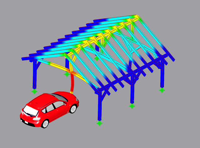
The fundamental requirements of a structural system are (according to the basis of structural design) sufficient ultimate limit state, serviceability, and resistance. Structures must be designed in such a way that no damage occurs due to events such as the impact of a vehicle.

- 001555
- Modeling | Loading
- RFEM 5
-
- RSTAB 8
- RF-TIMBER AWC 5
- TIMBER AWC 8
- RF-TIMBER CSA 5
- TIMBER CSA 8
- RF-TIMBER Pro 5
- TIMBER Pro 8
- RF-JOINTS Timber | Timber to Timber 5
- JOINTS Timber | Timber to Timber 8
- RF-JOINTS Timber | Steel to Timber 5
- JOINTS Timber | Steel to Timber 8
- RF-LIMITS 5
- LIMITS 8
- RF-LAMINATE 5
- Timber Structures
- Laminate and Sandwich Structures
- Structural Analysis & Design
- Finite Element Analysis
- Steel Connections
- Eurocode 0
- Eurocode 5
- ANSI/AISC 360
- SIA 260
- SIA 265
In addition to determining loads, some particularities concerning the load combinatorics in timber design have to be considered. Contrary to steel structures, where the largest loading results from all unfavorable actions, in timber construction, the strength values depend on the load duration and timber humidity. Special characteristics have to be considered as well for the serviceability limit state design. The following article discusses the effects on the design of wooden elements and how this is possible with RSTAB and RFEM.

In Germany, DIN EN 1991-1-4 with the National Annex DIN EN 1991-1-4/NA regulates the wind loads. The standard applies to civil engineering works up to an altitude of 300 m.

This article describes how a flat slab is generated as a 2D model in RFEM and the loading is applied according to Eurocode 1. The load cases are combined according to Eurocode 0 and calculated linearly. In the RF-CONCRETE Surfaces add-on module, the bending design of the slab is performed while taking into account the standard requirements of Eurocode 2. The reinforcement is complemented by a rebar reinforcement for areas that are not covered by the mesh basic reinforcement.