86 Results
View Results:
Sort by:

With the Steel Design add-on, you can design structural steel components in the event of fire using the simple design methods according to Eurocode 3. The component temperature at the time of the design check can be determined automatically according to the temperature-time curves specified in the standard. In addition to considering a cladding for fire protection, it is also possible for you to take account of the beneficial properties of hot-dip galvanization.

A new capability within RFEM 6 when designing concrete columns is being able to generate the moment interaction diagram according to the ACI 318-19 [1]. When designing reinforced concrete members, the moment interaction diagram is an essential tool. The moment interaction diagram represents the relationship between the bending moment and axial force at any given point along a reinforced member. Valuable information is shown visually like strength and how the concrete behaves under different loading conditions.

The design of cold-formed steel members according to the AISI S100-16 is now available in RFEM 6. Design can be accessed by selecting “AISC 360” as the standard in the Steel Design add-on. “AISI S100” is then automatically selected for the cold-formed design (Image 01).

Line releases are special objects in RFEM 6 that allow structural decoupling of objects connected to a line. They are mostly used to decouple two surfaces that are not rigidly connected or transferring only compressive forces at the common boundary line. By defining a line release, a new line is generated at the same place which transfers only the locked degrees of freedom. This article will show the definition of line releases in a practical example.

In this paper, a novel approach was developed to generate CFD models at the community-level by integrating building information modeling (BIM) and geographical information systems (GIS) to automate the generation of a high-resolution 3-D community model to be employed as an input for a digital wind tunnel using RWIND.
RWIND 2 is a program for generating wind loads based on CFD (Computational Fluid Dynamics). The wind flow numerical simulation is generated around any building, including irregular or unique geometry types, to determine the wind loads on surfaces and members. RWIND 2 can be integrated with RFEM/RSTAB for the structural analysis and design or as a stand-alone application.

The advantage of the RFEM 6 Steel Joints add-on is that you can analyze steel connections using an FE model for which the modeling runs fully automatically in the background. The input of the steel joint components that control the modeling can be done by defining the components manually, or by using the available templates in the library. The latter method is included in a previous Knowledge Base article titled “Defining Steel Joint Components Using the Library". The definition of parameters for the design of steel joints is the topic of the Knowledge Base article “Designing Steel Joints in RFEM 6".

RWIND 2 is a program for generating wind loads based on CFD (Computational Fluid Dynamics). The wind flow numerical simulation is generated around any building, including irregular or unique geometry types, to determine the wind loads on surfaces and members. RWIND 2 can be integrated with RFEM/RSTAB for the structural analysis and design or as a stand-alone application.

The effects due to snow load are described in the American standard ASCE/SEI 7-16 and in Eurocode 1, Parts 1 through 3. These standards are implemented in the new RFEM 6 program and the Snow Load Wizard, which serves to facilitate the application of snow loads. In addition to this, the most recent generation of the program allows the construction site to be specified on a digital map, thus allowing the snow load zone to be imported automatically. These data are, in turn, used by the Load Wizard to simulate the effects due to the snow load.

An FE mesh quality display is available in RFEM as a tool for structural analyses of two-dimensional components. It leads to the execution of an internal check of the generated finite elements for defined criteria.

In RFEM and RSTAB, there are various options to renumber the individual structural elements, such as nodes, lines, members, surfaces, or solids. Two options are available for renumbering: singly and automatically.
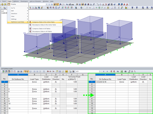
To ensure the well‑arranged structure of data in tables, the load data are organized automatically in RFEM and RSTAB.
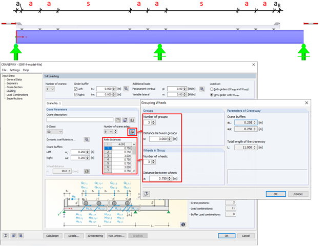
In CRANEWAY, the "Grouping Wheels" dialog box allows you to generate efficient groups with equal intervals.
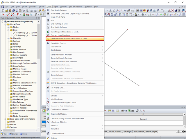
The "Generate Nodes at Intersection Points of Lines" option creates a node at the intersection points of lines without splitting the lines.
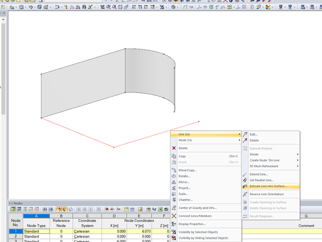
In RFEM, the function is implemented to generate a surface automatically from lines perpendicular to the work plane.
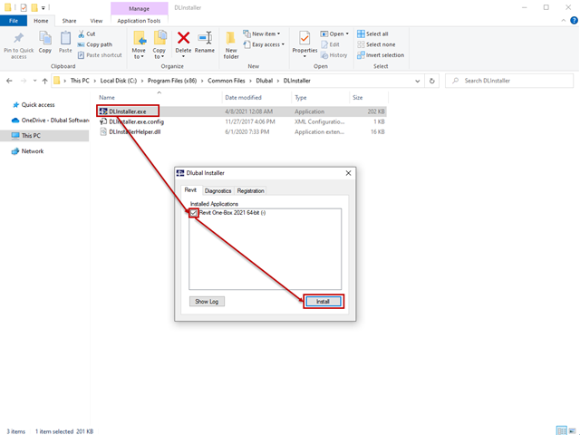
The interface to Autodesk Revit is installed automatically during the installation of RFEM 5 or RSTAB 8. Subsequent installation of the plug‑in is possible through the execution of Revit-Installer.exe.
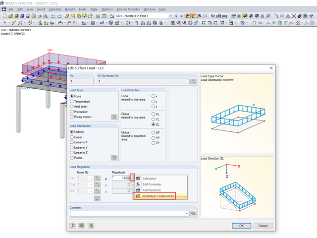
In RFEM and RSTAB, you can generate loads from multilayer composition.
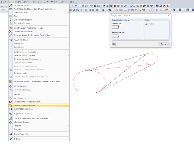
Various tools for modeling are available in RFEM. The modeling functions allow you to represent complex structures quickly and efficiently in the program. The connection of two circles or arcs, for example, can be generated with the "Tangent to Circles or Arcs" function.

For designing glass in the RF‑GLASS add‑on module, you can use one of two calculation methods: a 2D or a 3D calculation. The main difference between these design options is the automatic modeling of the layers in a temporary model. In a 2D calculation, each layer is generated as a surface element (plate theory); in a 3D calculation, it is generated as a solid. Depending on the selected layer composition, you can either select an option or find it preselected by the program.

In RF-/STEEL EC3, you can optimize a cross-section automatically within the design. To do this, select the corresponding cross-section in Table 1.3 or define variable parameters for a welded cross-section.
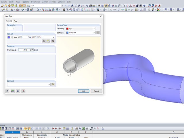
It may become necessary to analyze pipe cross‑sections as surface models in plant engineering in particular, but also when analyzing details of structural systems. For this purpose, RFEM offers the option to create pipe cross‑sections automatically by means of a line.

For automatic load case combination in RFEM and RSTAB, you have to enter the possible interaction of load cases. In addition to the simultaneous or alternative occurrence of all load cases of an action, an option for different combination conditions is possible.

In the default setting, the cross-section class for each member and load case is determined automatically in the design modules. In the input window of the cross sections, however, the user can also specify the cross-section class manually; for example, if local buckling is excluded by the design.
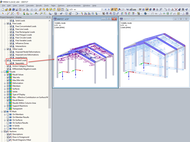
If, after defining the generated loads belonging together, you switch to the visibility mode, the loads are also shown on the hidden structural elements.
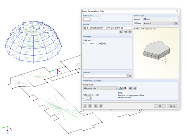
If you have imported a DXF file in RFEM or you need to add a membrane to an existing member structure, you can use the function "Tools" → "Generate Model - Surfaces" → "Surfaces from Cells", and thus quickly create planar surfaces.
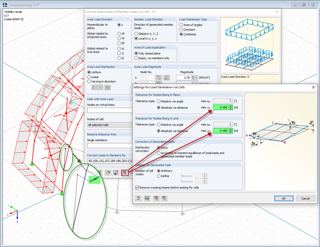
The load generators in RFEM and RSTAB, used to convert area loads to member loads automatically, require cells that are almost even. In the case of arc‑like structures, the cells often cannot be recognized automatically.

For the stability design of members and sets of members with a uniform cross-section, you can use the equivalent member method according to EN 1993-1-1, 6.3.1 to 6.3.3. However, as soon as a tapered cross-section is available, this method can no longer be used, or only used to a limited extent. The RF-/STEEL EC3 add-on module can automatically recognize these cases and switch to the general method.

In RFEM, surfaces are automatically connected if they have common boundary lines. If the definition line of a surface is lying in another surface, the line is automatically integrated into the surface, provided that it is a planar surface. For quadrangle surfaces, however, automatic object detection would be relatively time-consuming. For this reason, the corresponding function is deactivated. The integrated objects must be specified manually.
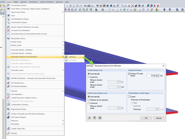
RFEM allows you to automatically generate surfaces from modeled members. This has the advantage that, for example, the surface thicknesses of a steel section are generated automatically.
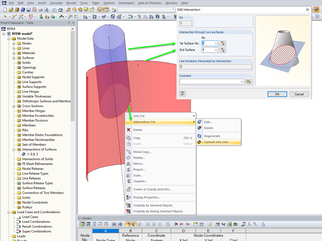
If you want to model two intersecting surfaces, RFEM offers you the possibility to create the section line automatically. In the program, this function is referred to as intersection. When generating an intersection, the modeled surface is split into components. This has the advantage that the components can be taken into account in the determination of the internal forces, or deactivated.