70 Results
View Results:
Sort by:

This article presents the basic concepts in structural dynamics and their role in the seismic design of structures. Great emphasis is given to explaining the technical aspects in an understandable way, so that readers without deep technical knowledge can gain an insight into the subject.

For the stability verification of members using the equivalent member method, it is necessary to define effective or lateral-torsional buckling lengths in order to determine a critical load for stability failure. In this article an RFEM 6-specific function is presented, by which you can assign an eccentricity to the nodal supports and thus influence the determination of the critical bending moment considered in the stability analysis.

In RFEM 6, the results for the FE mesh nodes are determined using the finite element method. For the distribution of internal forces, deformations, and stresses to be continuous, these nodal values are smoothed through an interpolation process. This article will introduce and compare the different types of smoothing that you can use for this purpose.

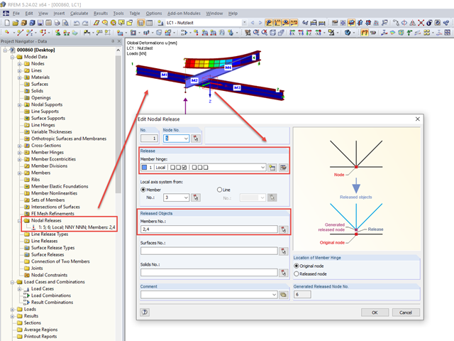
Nodal releases are special objects in RFEM 6 that allow structural decoupling of objects connected to a node. The release is controlled by the release type conditions, which may also have nonlinear properties. This article will show the definition of nodal releases in a practical example.

This article will show you the Building Model add-on, which has been enhanced with one important advantage: calculating the center of mass and center of rigidity.

The “Modal Analysis” add-on in RFEM 6 allows you to perform modal analysis of structural systems, thus determining natural vibration values such as natural frequencies, mode shapes, modal masses, and effective modal mass factors. These results can be used for vibration design, as well as for further dynamic analyses (for example, loading by a response spectrum).

The optimal scenario in which punching shear design according to ACI 318-19 [1] or CSA A23.3:19 [2] should be utilized is when a slab is experiencing a high concentration of loading or reaction forces occurring at one single node. In RFEM 6, the node in which punching shear is an issue is referred to as a punching shear node. The causes of these high concentration of forces can be introduced by a column, concentrated force, or nodal support. Connecting walls can also cause these concentrated loads at wall ends, corners, and ends of line loads and supports.

Given that realistic determination of the soil conditions significantly influences the quality of the structural analysis of buildings, the Geotechnical Analysis add-on is offered in RFEM 6 to determine the soil body to be analyzed.
The way to provide data obtained from field tests in the add-on and use the properties from soil samples to determine the soil massifs of interest was discussed in Knowledge Base article “Creation of the Soil Body from Soil Samples in RFEM 6”. This article, on the other hand, will discuss the procedure to calculate settlements and soil pressures for a reinforced concrete building.

The stand-alone program RSECTION is at your disposal for determining section properties and performing stress analysis for thin-walled and massive cross-sections. The program can be connected to both RFEM and RSTAB so that sections from RSECTION are also available in the RFEM and RSTAB library. Likewise, internal forces from RFEM and RSTAB can be imported into RSECTION.

You can use the stand-alone program RSECTION to determine the section properties for any thin-walled and massive cross-sections, as well as to perform a stress analysis. The previous Knowledge Base article titled "Graphical/Tabular Creation of User-defined Cross-sections in RSECTION 1" discussed the basis of defining cross-sections in the program. This article, on the other hand, is a summary of how to determine the section properties and perform a stress analysis.

Modal analysis is the starting point for the dynamic analysis of structural systems. You can use it to determine natural vibration values such as natural frequencies, mode shapes, modal masses, and effective modal mass factors. This outcome can be used for vibration design, and it can be used for further dynamic analyses (for example, loading by a response spectrum).

RSECTION 1 is a stand-alone program for determining section properties for both thin-walled and massive cross-sections, as well as for performing a stress analysis. In addition, the program can be connected to both RFEM and RSTAB: sections from RSECTION are available in the RFEM/RSTAB libraries, and internal forces from RFEM/RSTAB can be imported into RSECTION.

The punching shear design, in line with EN 1992-1-1, should be performed for slabs with a concentrated load or reaction. The node where the design of punching shear resistance is performed (that is, where there is a punching problem) is called a node of punching shear. The concentrated load at these nodes can be introduced by columns, concentrated force, or nodal supports. The end of the linear load introduction on slabs is also regarded as a concentrated load and therefore, the shear resistance at wall ends, wall corners, and ends or corners of line loads and line supports should be controlled as well.

The stability checks for the equivalent member design according to EN 1993-1-1, AISC 360, CSA S16, and other international standards require consideration of the design length (that is, the effective length of the members). In RFEM 6, it is possible to determine the effective length manually by assigning nodal supports and effective length factors or, on the other hand, by importing it from the stability analysis. Both options will be demonstrated in this article by determining the effective length of the framed column in Image 1.

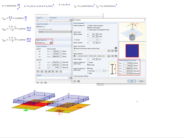
This article describes how a flat slab of a residential building is modeled in RFEM 6 and designed according to Eurocode 2. The plate is 24 cm thick and is supported by 45/45/300 cm columns at distances of 6.75 m in both the X and Y directions (Image 1). The columns are modeled as elastic nodal supports by determining the spring stiffness based on the boundary conditions (Image 2). C35/45 concrete and B 500 S (A) reinforcing steel are selected as the materials for the design.

The add-on modules for designing structural member components according to national, European, and international standards also show design results in addition to numerical output in tables graphically, as diagrams displayed on the framework.

The number of National Annexes for Eurocode 2 with regard to the design of reinforced concrete cross-sections has been extended since SHAPE-MASSIVE 6.54. Therefore, the following NAs of EN 1992-1-1:2004 + AC:2010 are available:
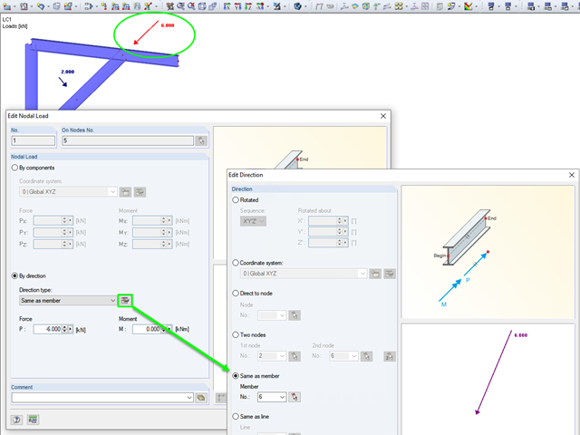
RFEM and RSTAB provide various options for entering nodal loads. These implemented features allow the user to define the nodal loads in relation to different components in space.
Occasionally, it is necessary to consider in a model that some beams only lie loosely on top of one another without screwing or welding.

The SHAPE‑THIN and SHAPE‑MASSIVE cross-section programs are suitable for determining the cross-section properties of common thin-walled or thick-walled sections. These cross-section properties are also available for further analyses in RSTAB and RFEM.

In the RF-GLASS add-on module, 3D rendering is implemented to facilitate the definition of the support conditions. This interactive graphical visualization facilitates the input and control of line and nodal supports. However, the schematic display can also be selected, if necessary.

The RF-/LIMITS add-on module allows you to compare the ultimate limit state of members, member ends, nodes, nodal supports, and surfaces (RFEM only) by means of a defined ultimate load capacity. Furthermore, you can check nodal displacements and cross-section dimensions. In this example, the column bases of a carport are to be compared with the maximum allowable forces specified by the manufacturer.

You can use the elastic support option to avoid singularities due to a fixed nodal support in RFEM. This can be defined directly in the dialog box of the nodal support as a column in Z. It is necessary to take into account the geometry of the column, the material, and the support conditions. Here, we want to look at the option of modeling the column as a surface foundation.
Often, it happens that stress peaks occur on a nodal support that is attached to a surface. You can avoid such singularities by modeling the nodal support as a column.

In RF‑/STEEL EC3, you can assign the same input data to several members or sets of members at the same time. The simultaneous assignment of the input data is possible for intermediate supports, effective lengths, nodal supports, member end hinges, and shear panel and rotational restraint.

Supports can be copied and moved using drag & drop, even if the "Move/Copy" function is not available in the shortcut menu. This applies to all kinds of supports: nodal supports, line supports, and surface supports. These can easily be assigned to further nodes, lines, or surfaces.
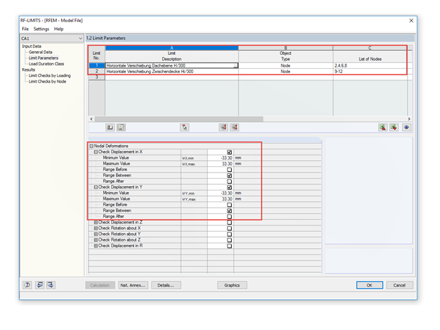
To control the lateral displacements of a model, you can use the RF-/LIMITS add‑on module. This add‑on module allows you to, for example, run a serviceability limit state analysis to find horizontal nodal deformations and to set it against a limit value.
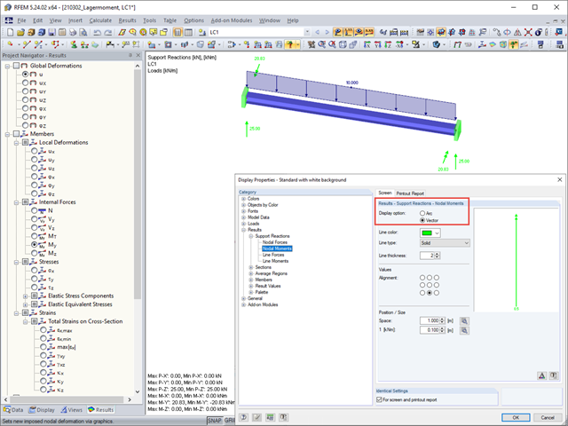
In the display properties, you can select Results → Support Reactions → Nodal Moments to specify whether a support moment should be displayed as an arc or a vector.
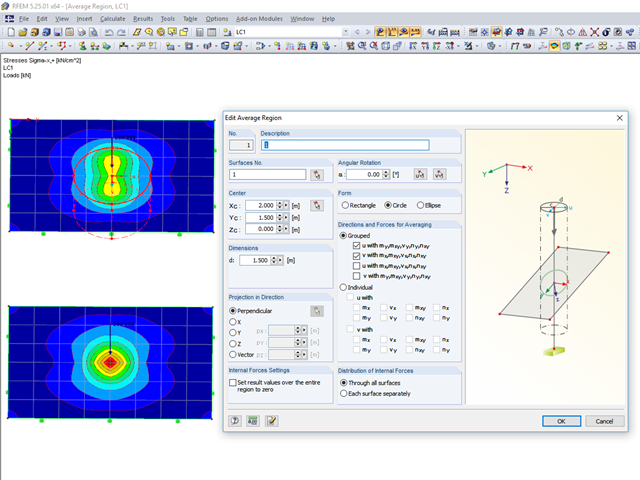
RFEM 5 provides the option to define a smoothing area in the "Results" → "New Average Region" menu. You can choose a rectangular, circular, or elliptical shape. With this tool you can, for example, "smooth" singularities due to nodal loads in a desired averaged region.
Structures react differently to wind action depending on stiffness, mass, and damping. A basic distinction is made between buildings that are prone to vibration and those that are not.