54 Wyniki
Wyświetl wyniki:
Sortuj według:

Rozszerzenie Projektowanie konstrukcji stalowych w RFEM 6 oferuje teraz możliwość przeprowadzania obliczeń sejsmicznych zgodnie z AISC 341-16 i AISC 341-22. Obecnie dostępnych jest pięć typów systemów sejsmicznych (SFRS).

Obliczenia zwykłej ramy stężonej koncentrycznie (OCBF) oraz SCBF (specjalnej konstrukcji szkieletowej stężonej koncentrycznie) można przeprowadzić w rozszerzeniu Projektowanie konstrukcji stalowych dla programu RFEM 6. Wyniki obliczeń sejsmicznych zgodnie z AISC 341-16 i 341-22 są podzielone na dwie sekcje: Wymagania dotyczące prętów i połączeń.

Obliczanie ramy momentowej zgodnie z AISC 341-16 jest teraz możliwe w rozszerzeniu Projektowanie konstrukcji stalowych dla programu RFEM 6. Wynik obliczeń sejsmicznych jest podzielony na dwie sekcje: wymagania dotyczące prętów i połączeń. W tym artykule omówiono wymaganą wytrzymałość połączenia. Przedstawiono przykładowe porównanie wyników pomiędzy RFEM a AISC Seismic Design Manual.

W rozszerzeniu Projektowanie konstrukcji stalowych dla programu RFEM 6 dostępne są trzy typy ram sprężystych (zwykłe, pośrednie i specjalne). Wyniki obliczeń sejsmicznych zgodnie z AISC 341-16 są podzielone na dwie sekcje: wymagania dotyczące prętów i połączeń.

W rozszerzeniu Projektowanie konstrukcji stalowych dla programu RFEM 6 dostępne są trzy typy ram sprężystych (zwykłe, pośrednie i specjalne). Wyniki obliczeń sejsmicznych zgodnie z AISC 341-22 są podzielone na dwie sekcje: wymagania dotyczące prętów i połączeń.
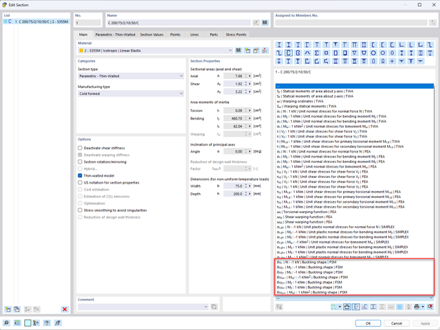
Aby umożliwić ocenę wpływu lokalnych zjawisk stateczności smukłych elementów, w programach RFEM 6 i RSTAB 9 można przeprowadzić liniową analizę obciążenia krytycznego na poziomie przekroju. Poniższy artykuł poświęcony jest podstawom obliczeń i interpretacji wyników.

Analiza modalna jest punktem wyjścia do analizy dynamicznej układów konstrukcyjnych. Można ją wykorzystać do określenia wartości drgań własnych, takich jak częstotliwości drgań własnych, kształty drgań własnych, masy modalne i efektywne współczynniki masy modalnej. Wynik ten może zostać wykorzystany do obliczeń drgań oraz do dalszych analiz dynamicznych (na przykład obciążenia widmem odpowiedzi).
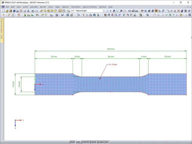
Deformacje sprężyste elementu konstrukcyjnego pod wpływem obciążenia są oparte na prawie Hooke'a, opisującym liniową zależność naprężenie-odkształcenie. Są one odwracalne: po odciążeniu element powraca do swojego pierwotnego kształtu. Jednakże deformacje plastyczne są nieodwracalne i zazwyczaj znacznie większe niż odkształcenia sprężyste. W przypadku naprężeń plastycznych materiałów ciągliwych, takich jak stal, efekty plastyczności występują w miejscach, w których wzrostowi odkształceń towarzyszy zjawisko lokalnego wzmocnienia. Prowadzi to do powstania trwałych deformacji, a w ekstremalnych przypadkach do zniszczenia elementu konstrukcyjnego.
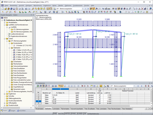
W poniższym artykule, na przykładzie dwukondygnacyjnej stalowej ramy, przeanalizowano wymiarowanie połączeń oraz wpływ sztywności tych połączeń na wartości sił wewnętrznych w elementach konstrukcji.
Przekątne podwójnych kątowników są stosowane między innymi do rurowej konstrukcji mostów i dźwigarów kratowych. Sie werden vorwiegend auf Zug beansprucht, müssen aber je nach Lastangriff auch kleinere Druckkräfte übertragen. Besonders wenn die Diagonalen sehr schlank sind, sollte auch Biegung aus Eigengewicht berücksichtigt werden.
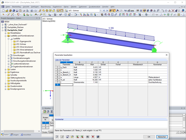
Niniejszy artykuł techniczny omawia analizę stateczności płatwi, która połączona jest z konstrukcją główną tylko poprzez przykręcenie dolnej półki profilu płatwii za pomocą śrub (bez dodatkowego podparcia bocznego). Połączenie takie ma na celu maksymalną redukcję kosztów i czasu produkcji.
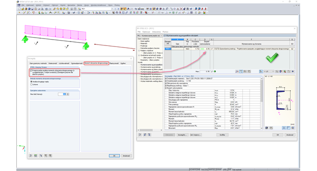
Rozszerzenie RF-/STEEL Warping Torsion dla modułu dodatkowego RF-/STEEL EC3 umożliwia wymiarowanie prętów o asymetrycznych przekrojach. Nowa opcja jest w pełni zintegrowana z modułem obliczeniowym i można ją aktywować dla zbiorów prętów.
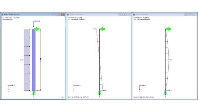
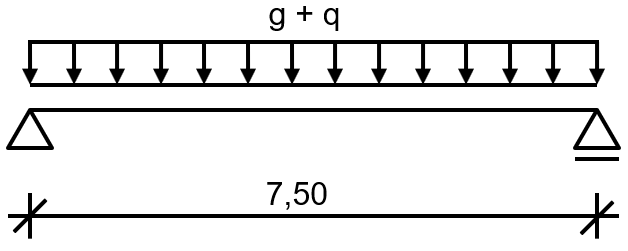
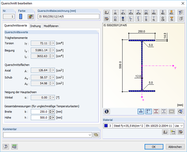
W poniższym artykule przedstawimy wymiarowanie słupa podpartego przegubowo na obydwu końcach zgodnie z EN 1993-1-1. Obciążenie stanowi skupiona siła osiowa oraz obciążenie liniowe działające na kierunku ”mocnej” osi bezwładności. Wykorzystany zostanie do tego moduł dodatkowy RF-/STEEL EC3.
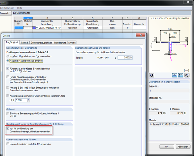
Am Beispiel soll gezeigt werden, was bei der Bemessung einer Stütze auf Biegung und Druck bezüglich der Schnittgrößen aus Lastkombinationen und Ergebniskombinationen beachtet werden muss.
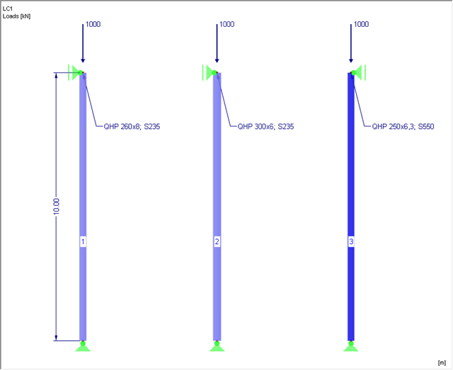
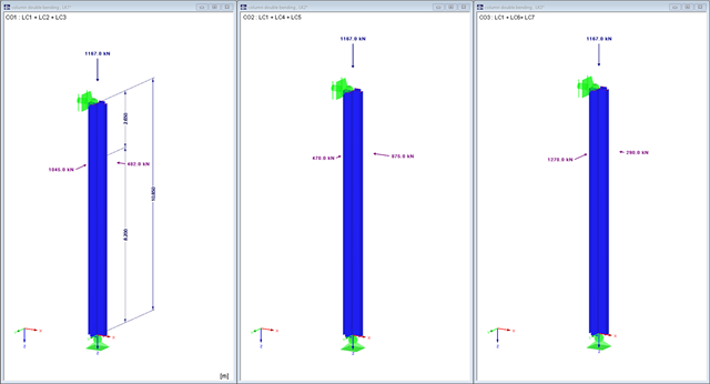
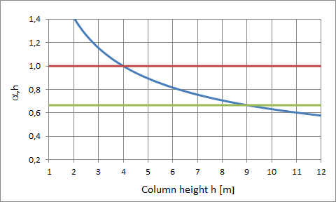
Niniejszy artykuł dotyczy analizy stateczności słupa stalowego poddanego ściskaniu osiowemu zgodnie z EN 1993-1-1, rozdz. 6.3.1. Zusätzlich wird eine Variantenuntersuchung mit dem Ziel der Stahloptimierung durchgeführt.
Das Schalenbeulen gilt als das jüngste und am wenigsten erforschte Stabilitätsproblem der Bautechnik. Dies liegt weniger an mangelnden Forschungsaufwendungen, sondern vielmehr an der Komplexität der Theorie. Mit der Einführung und Fortentwicklung der Finite-Elemente-Methode in der bautechnischen Praxis erscheint es manchem Ingenieur nicht mehr erforderlich, sich mit der komplizierten Theorie des Schalenbeulens auseinanderzusetzen. Zu welchen Problemen und Fehlern dies führen kann, ist in [1] sehr gut zusammengefasst.
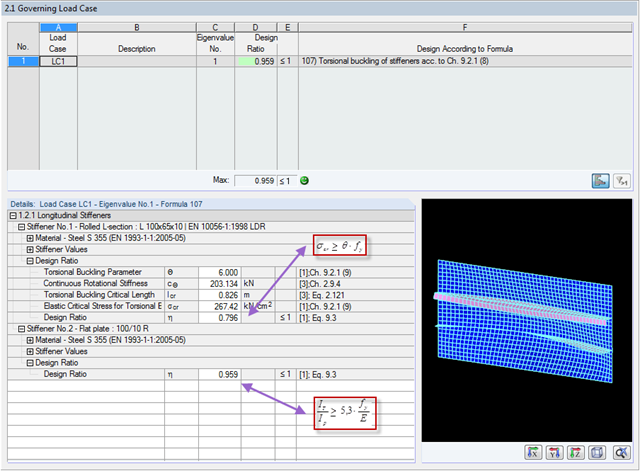
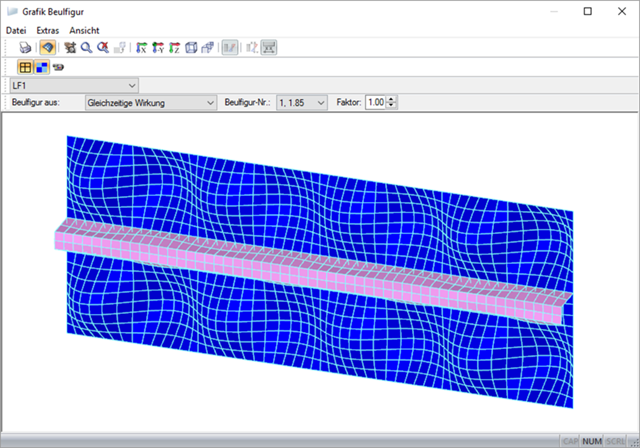
Analiza wyboczenia skrętnego usztywnień poprzecznych i podłużnych o otwartych przekrojach opisana jest w normie DIN EN 1993-1-5, rozdz. 9. Dabei wird zwischen einer vereinfachten und einer genauen Methode unterschieden, welche die Wölbsteifigkeit des Beulfeldes berücksichtigt. Vereinfachend gilt die Gleichung 9.3 der DIN EN 1993-1-5. Wird die Wölbsteifigkeit der Steife mit berücksichtigt, sollte entweder Gl. 9.3 oder Gl. 9.4 erfüllt werden. Beide Nachweise sind in FE-BEUL implementiert.
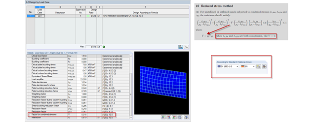
W styczniu 2015 r., DIN Committee NA 005‑08‑23 Steel Bridges zastosował modyfikację równania 10.5 w normie DIN EN 1993‑1‑5. Es handelt sich hierbei um die Interaktion von Längs- und Querdruck im Beulnachweis. Diese Interaktionsgleichung sieht nun den Hilfsfaktor V vor, welcher sich aus den Abminderungsfaktoren der Längs- und Querspannungen berechnet.
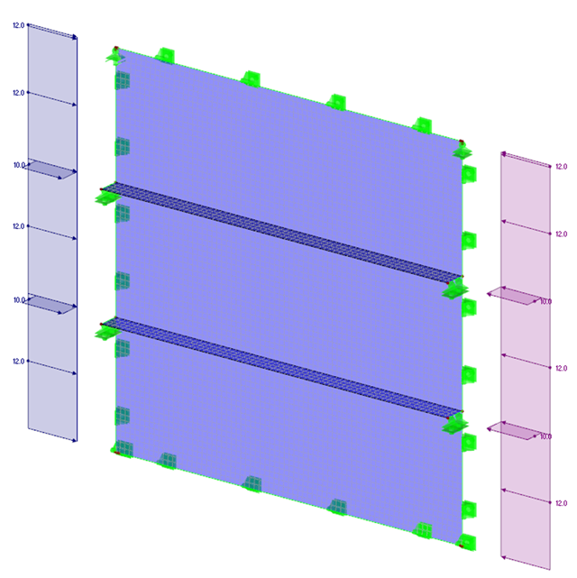
Analiza wyboczenia płyt z elementami usztywniającymi jest zadaniem specjalnym dla inżynierów. DIN EN 1993-1-5 stellt für diese Herausforderung drei Berechnungsverfahren zur Verfügung:Methode der wirksamen Querschnitte, [1], Kap. 4-7Methode der reduzierten Spannungen, [1], Kap. 10Berechnungen mit der Finite-Element-Methode (FEM), [1], Anhang C
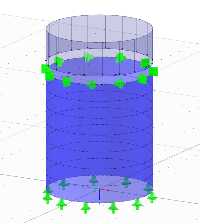
Analiza wyboczenia zgodnie z metodą szerokości efektywnej lub metodą zredukowanych naprężeń opiera się na określeniu obciążenia krytycznego układu, zwanej dalej LBA (liniowa analiza wyboczeniowa). W artykule tym wyjaśniono sposób obliczania współczynnika obciążenia krytycznego oraz zastosowanie metody elementów skończonych (MES).
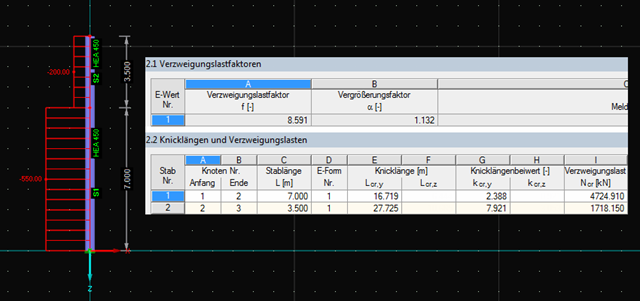
Moduły dodatkowe RF-STABILITY i RSBUCK dla programów RFEM i RSTAB umożliwiają przeprowadzanie analizy wartości własnych dla konstrukcji ramowych w celu określenia współczynników obciążenia krytycznego, w tym postaci wyboczenia. Można określić kilka postaci wyboczenia. Dostarczają one informacji na temat obszarów w modelu, obciążonych ryzykiem braku stateczności.
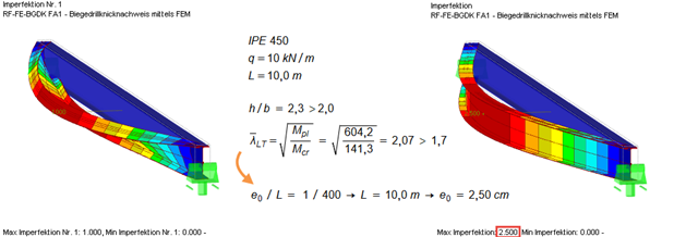
Zgodnie z normą EN 1993‑1‑1 [1] konieczne jest zastosowanie zastępczych imperfekcji geometrycznych o wartościach odzwierciedlających możliwe efekty wszystkich typów imperfekcji. In EN 1993‑1‑1 Abschnitt 5.3 werden die grundsätzlichen Imperfektionen für die Tragwerksberechnung sowie die Bauteilimperfektionen angegeben.
Zgodnie z normą EN 1993-1-1 [1] konieczne jest zastosowanie zastępczych imperfekcji geometrycznych o wartościach odzwierciedlających możliwe efekty wszystkich typów imperfekcji. In EN 1993-1-1 Abschnitt 5.3 werden die grundsätzlichen Imperfektionen für die Tragwerksberechnung sowie die Bauteilimperfektionen angegeben.
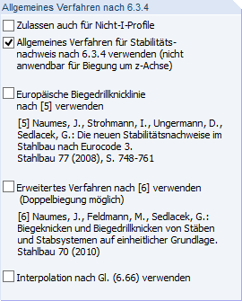
Oprócz obliczeń stateczności zgodnie z EN 1993‑1‑1, Sekcje 6.3.1 do 6.3.3, w RF‑/STEEL EC3 można zastosować metodę ogólną zgodną z EN 1993‑1‑1, 6.3.4.

W tym artykule technicznym omówimy podstawowe kwestie dotyczące korzystania z rozszerzenia Skręcanie skrępowane (7 stopni swobody). Jest ono w pełni zintegrowane z programem głównym i umożliwia uwzględnienie deplanacji przekroju podczas obliczania elementów prętowych. W połączeniu z rozszerzeniami Analiza stateczności oraz Wymiarowanie stali, możliwe jest przeprowadzenie obliczeń wyboczenia giętno-skrętnego z siłami wewnętrznymi zgodnie z analizą drugiego rzędu oraz uwzględnieniem imperfekcji.
Der Brandschutznachweis kann in RF-/STAHL EC3 nach EN 1993-1-2 geführt werden. Die Bemessung erfolgt nach dem vereinfachten Berechnungsverfahren auf der Tragfähigkeitsebene. Als Brandschutzmaßnahmen können Bekleidungen mit verschiedenen physikalischen Eigenschaften gewählt werden. Es stehen die Einheits-Temperaturzeitkurve, Außenbrandkurve sowie die Hydrokarbon-Brandkurve für die Ermittlung der Gastemperatur zur Auswahl.
Belka jednoprzęsłowa z podparciem bocznym i skrętnym powinna być zaprojektowana zgodnie z zaleceniami Eurokodu 3 i AISC. Falls der Träger die geforderte Tragfähigkeit nicht erreicht, ist dieser zu stabilisieren.

Osłony przeciwwiatrowe to specjalne konstrukcje tekstylne, które mają za zadanie chronić środowisko przed szkodliwymi cząsteczkami chemicznymi, jak również ograniczać erozję wietrzną, przyczyniając się do ochrony cennych zasobów. RFEM i RWIND są używane do analizy konstrukcji wiatrowej dla jednostronnej interakcji płyn-konstrukcja (FSI).
W tym artykule pokazano, jak wymiarować osłony przeciwwiatrowe przy użyciu programów RFEM i RWIND.
W tym artykule pokazano, jak wymiarować osłony przeciwwiatrowe przy użyciu programów RFEM i RWIND.

Zaletą modułu dodatkowego RFEM 6 Steel Joints jest możliwość analizy połączeń stalowych przy użyciu modelu MES, dla którego modelowanie przebiega w pełni automatycznie w tle. Elementy składowe złącza stalowego, które kontrolują modelowanie, można wprowadzić, definiując je ręcznie lub korzystając z dostępnych szablonów w bibliotece. Ta ostatnia metoda została opisana w poprzednim artykule z Bazy wiedzy zatytułowanym „Definiowanie komponentów połączenia stalowego przy użyciu biblioteki”. Definiowanie parametrów do wymiarowania połączeń stalowych jest tematem artykułu w bazie wiedzy „Projektowanie połączeń stalowych w RFEM 6”.

Ocena przemieszczenia kondygnacji w budynku jest kluczowa dla zapewnienia zadowalających parametrów konstrukcyjnych poprzez ograniczenie przemieszczenia kondygnacji. Nadmierne znoszenie może powodować niestateczność systemu i powodować uszkodzenia elementów niekonstrukcyjnych, takich jak ściany działowe. W tym artykule opisano procedurę wyznaczania przemieszczeń międzykondygnacyjnych zgodnie z ASCE 7-22 i rozszerzeniem Model budynku w programie RFEM 6.