40 Wyniki
Wyświetl wyniki:
Sortuj według:

Aby ocenić, czy w obliczeniach dynamicznych konieczne jest również uwzględnienie analizy drugiego rzędu, w normie EN 1998‑1, sekcje 2.2.2 i 4.4.2.2 zawarto współczynnik wrażliwości międzykondygnacyjnego znoszenia θ. Można ją obliczyć i przeanalizować za pomocą programów RFEM 6 i RSTAB 9.
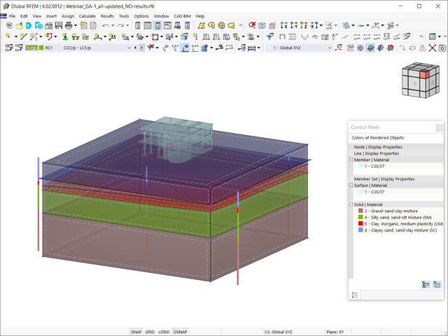
W tym artykule omówiono wyniki analizy geotechnicznej oraz ich graficzne i tabelaryczne przedstawienie w programie RFEM 6.

Jeżeli, na przykład, do określenia sił wewnętrznych ma zostać zastosowany model czysto powierzchniowy, ale wymiarowanie komponentu nadal odbywa się na modelu prętowym, można skorzystać z belki wynikowej.

Wyboczenie giętno-skrętne (LTB) jest zjawiskiem, które występuje, gdy belka lub element konstrukcyjny są zginane, a pas ściskany nie jest wystarczająco podparty bocznie. Prowadzi to do kombinacji przemieszczenia bocznego i skręcenia. Jest to decydujący czynnik przy wymiarowaniu elementów konstrukcyjnych, zwłaszcza smukłych belek i dźwigarów.

Rozszerzenie Wymiarowanie betonu umożliwia wymiarowanie słupów betonowych zgodnie z ACI 318-19. Poniższy artykuł potwierdzi wymiarowanie zbrojenia w rozszerzeniu Wymiarowanie betonu przy użyciu równań analitycznych krok po kroku zgodnie z normą ACI 318-19, w tym wymagane zbrojenie podłużne, pole przekroju brutto i rozmiar/rozstaw ściągu.

W programie RFEM 6 połączenia stalowe definiuje się jako układ elementów. W nowym rozszerzeniu Połączenia stalowe dostępne są podstawowe komponenty do uniwersalnego zastosowania (blachy, spoiny, płaszczyzny pomocnicze). Metody definiowania połączeń opisano w dwóch poprzednich artykułach w Bazie informacji: „Nowe podejście do wymiarowania połączeń stalowych w programie RFEM 6” oraz „Definiowanie elementów połączenia stalowego przy użyciu biblioteki” .

W tym artykule opisano, w jaki sposób płaska płyta budynku mieszkalnego jest modelowana w programie RFEM 6 i wymiarowana zgodnie z Eurokodem 2. Płyta ma grubość 24 cm i jest podparta na słupach o długości 45/45/300 cm w rozstawie co 6,75 m (rysunek 1). Słupy są modelowane jako sprężyste podpory węzłowe poprzez zdefiniowanie sztywności sprężystej na podstawie warunków brzegowych (rysunek 2). Jako materiały wybrano beton C35/45 i stal zbrojeniową B 500 S (A).

Rozszerzenie Projektowanie konstrukcji aluminiowych dla RFEM 6 wymiaruje pręty aluminiowe ze względu na stan graniczny nośności i użytkowalności zgodnie z Eurokodem 9. Ponadto możliwe jest wymiarowanie zgodnie z ADM 2020 (norma amerykańska).

Zgodnie z EN 1992-1-1 [1] belka jest prętem, którego rozpiętość jest nie mniejsza niż 3-krotna całkowita wysokość przekroju. W przeciwnym razie element konstrukcyjny należy traktować jako belkę-ścianę. Zachowanie belek-ścian (tj. belek o rozpiętości mniejszej niż 3-krotna wysokość przekroju) różni się od zachowania belek-ścian (tj. belek o rozpiętości trzykrotnie większej niż wysokość przekroju).
Projektowanie belek-ścian jest jednak często konieczne podczas analizy elementów konstrukcyjnych konstrukcji żelbetowych, ponieważ są one wykorzystywane do budowy nadproży okiennych i drzwiowych, podciągów i podciągów, połączeń między płytami dwupoziomowymi oraz konstrukcji ramowych.
Projektowanie belek-ścian jest jednak często konieczne podczas analizy elementów konstrukcyjnych konstrukcji żelbetowych, ponieważ są one wykorzystywane do budowy nadproży okiennych i drzwiowych, podciągów i podciągów, połączeń między płytami dwupoziomowymi oraz konstrukcji ramowych.

W tym artykule pokażemy, jak zdefiniować żebra podłużne na blasze pręta za pomocą komponentu „Żebro” w rozszerzeniu Połączenia stalowe.

Zarówno analiza drgań własnych, jak i analiza spektrum odpowiedzi przeprowadzane są na układzie liniowym. Jeżeli w modelu występują nieliniowości, podlega on linearyzacji, dzięki czemu elementy nieliniowe nie są brane pod uwagę w dalszej analizie. Mogą to być na przykład pręty rozciągane, podpory nieliniowe lub przeguby nieliniowe. W tym artykule pokazano, w jaki sposób można nimi zarządzać w analizie dynamicznej.

W tym artykule opisano na przykładzie płyty z betonu włóknistego, które wpływają na zastosowanie różnych metod całkowania i różnej liczby punktów całkowania na wynik obliczeń.

W tym artykule opisujemy, w jaki sposób można używać rozszerzenia Skręcanie skrępowane (7 stopni swobody) i Stateczność konstrukcji w celu uwzględnienia deplanacji przekroju jako dodatkowego stopnia swobody podczas analizy stateczności.

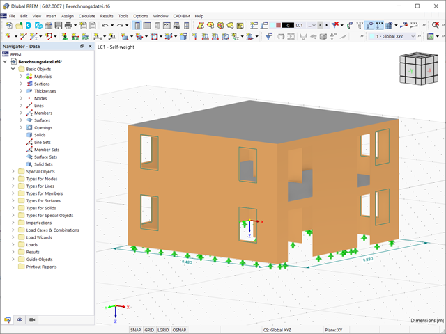
Jakość analizy statyczno-wytrzymałościowej budynków jest dużo lepsza, gdy można uwzględnić warunki gruntowe w sposób możliwie najbardziej realistyczny. W programie RFEM 6 można realistycznie określić kontur glebowy do analizy za pomocą rozszerzenia Analiza geotechniczna. Ten dodatek można aktywować w danych bazowych modelu, jak pokazano na rysunku 01.
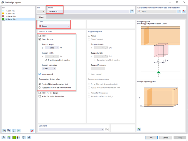
Standardowym rozwiązaniem w konstrukcji prętów drewnianych jest możliwość łączenia mniejszych prętów poprzez podparcie na większym dźwigarze. Dodatkowo warunki na końcach pręta mogą uwzględniać podobną sytuację, w której belka jest oparta na podporze. W obu przypadkach belka musi być zaprojektowana tak, aby uwzględniała nośność w poprzek włókien zgodnie z NDS 2018 s. 3.10.2 i CSA O86:19 punkty 6.5.6 i 7.5.9. W ogólnych programach do projektowania statyczno-wytrzymałościowego zazwyczaj nie jest możliwe przeprowadzenie pełnej kontroli obliczeń, ponieważ powierzchnia docisku jest nieznana. Jednak w programie RFEM 6 nowej generacji i rozszerzeniu Projektowanie konstrukcji drewnianych dodana funkcja "podpór obliczeniowych" umożliwia teraz użytkownikom uwzględnienie docisku NDS i CSA prostopadle do warunków obliczeniowych.

Zrozumienie sztywności połączeń stalowych ma kluczowe znaczenie w projektowaniu konstrukcji. Często połączenia są traktowane jako połączenia całkowicie sztywne lub przegubowe, co może prowadzić do nieekonomicznych lub nawet ryzykownych warunków projektowych. Dowiedz się, w jaki sposób program RFEM firmy Dlubal i rozszerzenie Połączenia stalowe pomagają weryfikować sztywność połączeń i nośność na zginanie, zapewniając bezpieczniejsze i bardziej ekonomiczne warunki projektowe.

Obliczenia ze względu na zmęczenie zgodnie z EN 1992-1-1 należy przeprowadzać w przypadku elementów konstrukcyjnych, które są poddane działaniu dużych zakresów naprężeń i/lub wielu zmianom obciążenia. W takim przypadku obliczenia dla betonu i zbrojenia są przeprowadzane osobno. Dostępne są dwie alternatywne metody obliczeniowe.
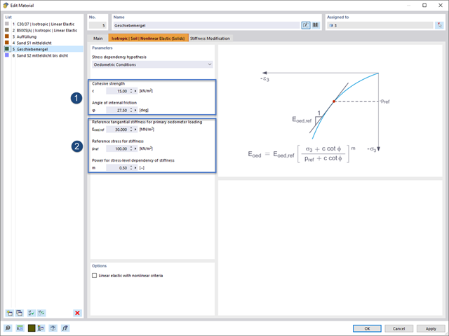
Rozszerzenie Analiza geotechniczna zapewnia programowi RFEM dodatkowe specyficzne modele materiałowe podłoża, które mogą odpowiednio odwzorować złożone zachowanie materiału podłoża. W tym artykule zaprezentujemy, w jaki sposób można określić zależną od naprężeń sztywność modeli materiałowych gruntu.

Ocena przemieszczenia kondygnacji w budynku jest kluczowa dla zapewnienia zadowalających parametrów konstrukcyjnych poprzez ograniczenie przemieszczenia kondygnacji. Nadmierne znoszenie może powodować niestateczność systemu i powodować uszkodzenia elementów niekonstrukcyjnych, takich jak ściany działowe. W tym artykule opisano procedurę wyznaczania przemieszczeń międzykondygnacyjnych zgodnie z ASCE 7-22 i rozszerzeniem Model budynku w programie RFEM 6.

Zaletą modułu dodatkowego RFEM 6 Steel Joints jest możliwość analizy połączeń stalowych przy użyciu modelu MES, dla którego modelowanie przebiega w pełni automatycznie w tle. Elementy składowe złącza stalowego, które kontrolują modelowanie, można wprowadzić, definiując je ręcznie lub korzystając z dostępnych szablonów w bibliotece. Ta ostatnia metoda została opisana w poprzednim artykule z Bazy wiedzy zatytułowanym „Definiowanie komponentów połączenia stalowego przy użyciu biblioteki”. Definiowanie parametrów do wymiarowania połączeń stalowych jest tematem artykułu w bazie wiedzy „Projektowanie połączeń stalowych w RFEM 6”.

W tym artykule technicznym omówimy podstawowe kwestie dotyczące korzystania z rozszerzenia Skręcanie skrępowane (7 stopni swobody). Jest ono w pełni zintegrowane z programem głównym i umożliwia uwzględnienie deplanacji przekroju podczas obliczania elementów prętowych. W połączeniu z rozszerzeniami Analiza stateczności oraz Wymiarowanie stali, możliwe jest przeprowadzenie obliczeń wyboczenia giętno-skrętnego z siłami wewnętrznymi zgodnie z analizą drugiego rzędu oraz uwzględnieniem imperfekcji.

Nowa generacja oprogramowania RFEM umożliwia przeprowadzanie obliczeń stateczności zbieżnych prętów drewnianych zgodnie z metodą prętów zastępczych. Zgodnie z tą metodą obliczenia można przeprowadzić, jeżeli spełnione są wytyczne normy DIN 1052, sekcja E8.4.2 dla zmiennych przekrojów. W różnych publikacjach technicznych metoda ta jest również stosowana w przypadku Eurokodu 5. W tym artykule pokazano, jak zastosować metodę prętów zastępczych dla belki dachowej o zbieżnej wysokości.
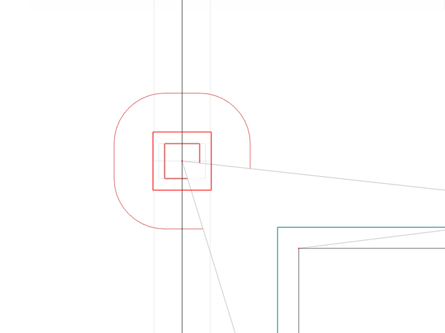
Obliczenia na przebicie zgodnie z EN 1992-1-1 należy przeprowadzić dla płyt poddanych obciążeniu skupionemu lub reakcji. Węzeł, w którym przeprowadzana jest analiza nośności na przebicie (tj. w miejscu, w którym występuje problem z przebiciem) nazywany jest węzłem odporności na przebicie. Obciążenie skupione w tych węzłach może zostać wprowadzone przez słupy, siłę skupioną lub podpory węzłowe. Koniec przyłożenia obciążenia liniowego na płyty również jest traktowany jako obciążenie skupione, dlatego należy również kontrolować nośność na ścinanie na końcach, narożach i końcach ścian oraz na końcach lub narożach obciążeń liniowych i podpór liniowych.

Jedną z innowacji w programie RFEM 6 jest nowy sposób projektowania połączeń stalowych. W przeciwieństwie do programu RFEM 5, w którym wymiarowanie połączeń stalowych opiera się na rozwiązaniu analitycznym, rozszerzenie Połączenia stalowe w programie RFEM 6 oferuje rozwiązanie dla połączeń stalowych w oparciu o analizę MES.
,_Table_22.5.5.1_ACI_318-19.png?mw=640&hash=7e50d54e01238943fe1c691c0aa197d9b2fa8511)
W najnowszej normie ACI 318-19 długoterminowa zależność w określaniu nośności betonu na ścinanieVc zostaje przedefiniowana. Dzięki nowej metodzie wysokość pręta, stopień zbrojenia podłużnego i naprężenie normalne wpływają teraz na wytrzymałość na ścinanie Vc. W poniższym artykule opisano zaktualizowane podejście do obliczeń dla ścinania, a zastosowanie przedstawiono na przykładzie.

Z tego artykułu dowiesz się, jak zamodelować proste połączenie z blachą czołową w programie RFEM 6.
Konstrukcje murowe można modelować i analizować w programie RFEM 6 za pomocą rozszerzenia Projektowanie konstrukcji murowych, który wykorzystuje do obliczeń metodę elementów skończonych. Zakładając, że w programie zaimplementowano nieliniowy model materiałowy, można modelować złożone konstrukcje murowe oraz przeprowadzać analizę statyczną i dynamiczną, aby przedstawić nośność konstrukcji murowej oraz różne mechanizmy uszkodzenia. Istnieje możliwość wprowadzania i modelowania konstrukcji murowych bezpośrednio w programie RFEM 6 oraz łączenia modelu materiałowego muru ze wszystkimi popularnymi rozszerzeniami dla programu RFEM. Umożliwia to projektowanie całych modeli budynków w połączeniu z murem.

W tym artykule przedstawiono model połączenia zakładkowego płatwi ZL na dachu jednospadowym, obliczony w rozszerzeniu Połączenia stalowe i porównany z tabelą nośności podaną przez producenta.
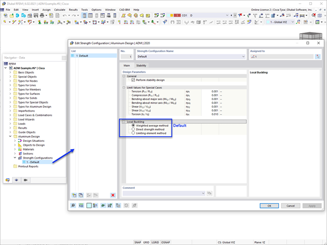
W tym artykule omówiono dostępne opcje określania nominalnej wytrzymałości na zginanie Mnlb dla stanu granicznego wyboczenia lokalnego, podczas projektowania zgodnie z Aluminium Design Manual (Podręcznik projektowania konstrukcji aluminiowych 2020).
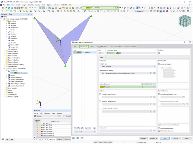
Program RFEM 6 zawiera rozszerzenie Form-Finding do określania kształtów równowagi modeli powierzchni obciążonych rozciąganiem i prętów obciążonych siłami osiowymi. Aktywuj ten dodatek w Danych bazowych modelu i użyj go, aby znaleźć położenie geometryczne, w którym naprężenie wstępne lekkich konstrukcji jest w równowadze z istniejącymi warunkami brzegowymi.