41 Wyniki
Wyświetl wyniki:
Sortuj według:

Z tego artykułu dowiesz się, jak modelować usztywnione połączenia rurowe w rozszerzeniu Połączenia stalowe.

Podczas obliczania siły tnącej w programie Wymiarowanie betonu zbrojonego, działającą siłę tnącą Vz można zredukować zgodnie z EN 1992-1-1. Poniższy artykuł opisuje redukcję siły tnącej od obciążeń skupionych w pobliżu podpory oraz wymiarowanie sił tnących w odległości d od krawędzi podpory w przypadku obciążenia równomiernie rozłożonego.
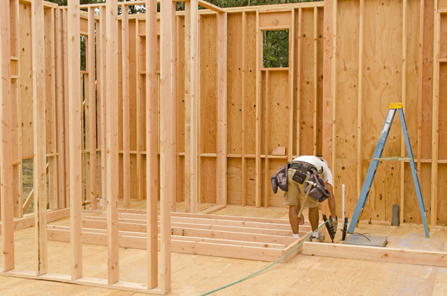
Obliczanie ściany drewnianej zbudowanej z paneli za pomocą grubości typu Drewniany panel szkieletowy
W tym artykule porównano obliczenia drewnianej ściany z paneli za pomocą grubości typu "Drewniany panel szkieletowy" z obliczeniami ręcznymi.

Jeżeli, na przykład, do określenia sił wewnętrznych ma zostać zastosowany model czysto powierzchniowy, ale wymiarowanie komponentu nadal odbywa się na modelu prętowym, można skorzystać z belki wynikowej.
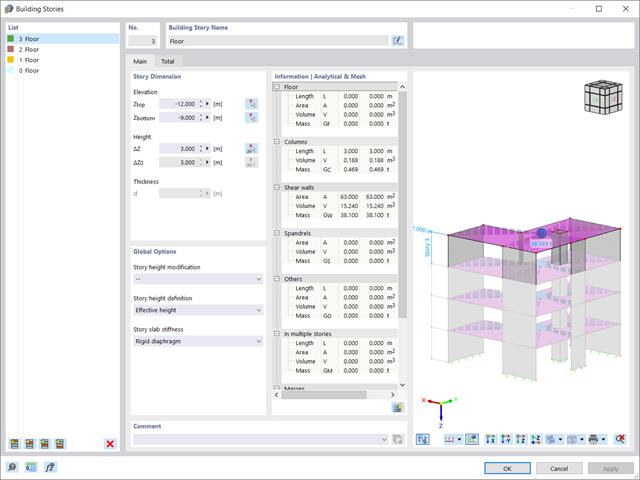
W tym artykule przedstawimy rozszerzenie Model budynku, które zostało wzbogacone o jedną ważną zaletę: obliczanie środka masy i środka sztywności.
Przy użyciu specjalnego przegubu liniowego dostępnego w programie RFEM 6 można poprawnie uwzględnić podczas modelowania właściwości połączenia płyty żelbetowej ze ścianą murowaną. Z tego artykułu dowiesz się, jak zdefiniować ten typ przegubu na praktycznym przykładzie.
W tym artykule przedstawimy Państwu "Dostosowanie wyników powierzchni" w RFEM 6, odpowiadające funkcji "Obszar uśredniania" zaimplementowanej w RFEM 5.
Wraz z programami do analizy statyczno-wytrzymałościowej RFEM 6, RSTAB 9, RSECTION 1 i RWIND 2, Dlubal Software przedstawia nową generację programów do analizy statyczno-wytrzymałościowej. Getreu dem Motto „Statik, die Spaß macht…“ werden den Anwendern universelle Werkzeuge in die Hand gegeben, mit denen alle Anforderungen in der Tragwerksplanung bewältigt werden können. Was sich sonst noch bei Dlubal Software Neues getan hat, erfahren Sie in diesem Artikel.

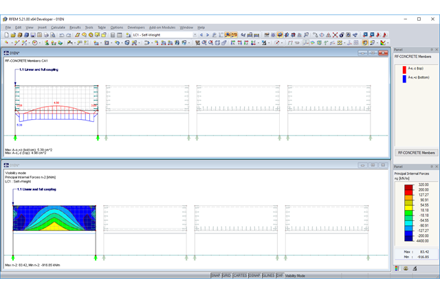
Zgodnie z EN 1992-1-1 [1] belka jest prętem, którego rozpiętość jest nie mniejsza niż 3-krotna całkowita wysokość przekroju. W przeciwnym razie element konstrukcyjny należy traktować jako belkę-ścianę. Zachowanie belek-ścian (tj. belek o rozpiętości mniejszej niż 3-krotna wysokość przekroju) różni się od zachowania belek-ścian (tj. belek o rozpiętości trzykrotnie większej niż wysokość przekroju).
Projektowanie belek-ścian jest jednak często konieczne podczas analizy elementów konstrukcyjnych konstrukcji żelbetowych, ponieważ są one wykorzystywane do budowy nadproży okiennych i drzwiowych, podciągów i podciągów, połączeń między płytami dwupoziomowymi oraz konstrukcji ramowych.
Projektowanie belek-ścian jest jednak często konieczne podczas analizy elementów konstrukcyjnych konstrukcji żelbetowych, ponieważ są one wykorzystywane do budowy nadproży okiennych i drzwiowych, podciągów i podciągów, połączeń między płytami dwupoziomowymi oraz konstrukcji ramowych.
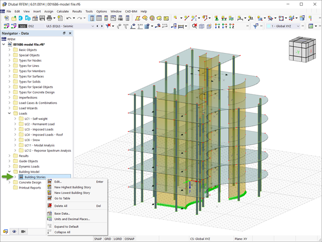
W programie RFEM 6 analizę sejsmiczną można przeprowadzić za pomocą modułów dodatkowych Analiza modalna i Analiza spektrum odpowiedzi. Zaraz po zakończeniu analizy spektralnej za pomocą rozszerzenia Model budynku można wyświetlić oddziaływania kondygnacji, przemieszczenia kondygnacji i siły w ścianach usztywniających.
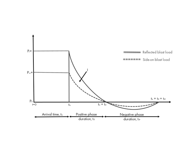
Obciążenia eksplozją od materiałów wybuchowych o dużej energii, przypadkowe lub celowe, są rzadkie, ale mogą być wymogiem projektowym. Obciążenia dynamiczne tego typu różnią się od normalnych obciążeń statycznych – są to obciążenia o znacznej wartości, ale oddziałujące bardzo krótkotrwale. Scenariusz eksplozji można przeprowadzić bezpośrednio w programie MES jako analizę historii czasowej, aby zminimalizować utratę żywotności i ocenić różne poziomy uszkodzeń konstrukcji.
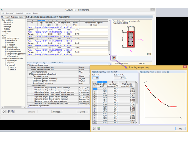
Wymiarowanie betonu zbrojonego na wypadek pożaru przeprowadza się zgodnie z metodą uproszczoną opartą na normie EN 1992-1-2, rozdz. 4.2. Dabei wird die im Anhang B.2 beschriebene "Zonenmethode" benutzt: Der Querschnitt wird in eine Anzahl paralleler Zonen gleicher Dicke unterteilt und deren temperaturabhängige Druckfestigkeit ermittelt. Die reduzierte Tragfähigkeit bei Brandeinwirkung wird so durch einen verkleinerten Bauteilquerschnitt mit abgeminderten Festigkeiten abgebildet.
Ponieważ w Eurokodzie nie uwzględniono wiatru oddziałującego na konstrukcje otwarte z jednej strony, odniesiono się do czterech przypadków z niemieckiej normy DIN 1055, część czwarta.
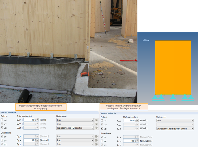
Na szczególną uwagę zasługuje podpora z płyty z drewna klejonego krzyżowo. Zazwyczaj, ściana z drewna klejonego krzyżowo jest zabezpieczona przed ścinaniem dzięki trzpieniom oraz przed siłą unoszącą za pomocą krzyżaków/prętów ściągających.
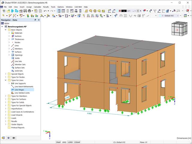
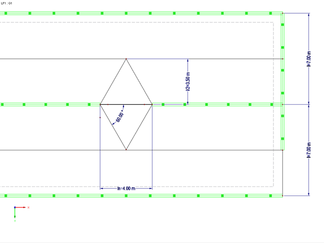
Jedną z zalet wprowadzania konstrukcji w programie RFEM jest pełna dowolność przy wyborze geometrii. Można łatwo wybrać konstrukcję, w której narożniki wklęsłe i faliste, jak pokazano na rysunku.
Konstrukcje różnie reagują na działanie wiatru, w zależności od sztywności, masy i tłumienia. Zasadniczo rozróżnia się budynki, które są podatne na drgania oraz takie, które nie są na nie podatne.
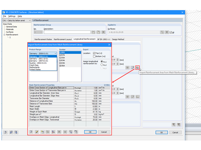
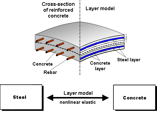
Beton charakteryzuje się głównie wytrzymałością na ściskanie. Ważną częścią betonu zbrojonego jest stal zbrojeniowa, która ma wpływ zarówno na wytrzymałość betonu na ściskanie, jak i na rozciąganie. Siatka zbrojeniowa jest zazwyczaj umieszczana w obszarach rozciąganych belek lub elementów powierzchniowych (strop, ściana, powłoka) w celu przenoszenia sił rozciągających wywołanych obciążeniami zewnętrznymi.
Zgodnie z wytycznymi DAfStb z broszury 631, Rozdział 2.4, sposób pracy płyt stropowych zmienia się, jeżeli ciągłość podparcia liniowego zostanie zakłócona przez wprowadzenie otworów w ścianach nośnych. W zależności od długości otworu i grubości płyty stropowej, konieczne jest przeprowadzenie dodatkowej analizy stropu w rejonie otworu.
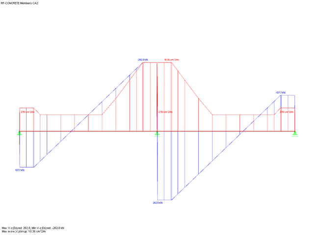
W przypadku obliczania siły tnącej w RF-CONCRETE Members i CONCRETE, działającą siłę tnącą Vz można zredukować zgodnie z EN 1992-1-1. Poniższy artykuł opisuje redukcję siły tnącej od obciążeń skupionych w pobliżu podpory oraz wymiarowanie sił tnących w odległości d od krawędzi podpory w przypadku obciążenia równomiernie rozłożonego.
Jeżeli żebro w stropie jest elementem konstrukcji obliczanej nieliniowo lub jest sztywno zamocowane w ścianach dochodzących, do jego modelowania należy użyć powierzchni zamiast pręta. Aby żebro nadal mogło być zaprojektowane jako element prętowy, należy zdefiniować belkę wynikową o prawidłowym mimośrodzie, która pozwala odczytać siły wewnętrzne w powłoce jako siły wewnętrzne dla równoważnego pręta.
.png?mw=640&hash=2c777f8924370109f41757e8517fd5d08108c956)
Poniższe opracowanie porównuje ciśnienie wiatru na wysoki budynek, uzyskane przez RWIND Simulation z wynikami opublikowanymi przez Dagnew et al. podczas11th Americas Conference on Wind Engineering w czerwcu 2009 r. W niniejszym artykule jako model wykorzystano budynek Commonwealth Advisory Aeronautical Council (CAARC), a wyniki kilku różnych metod numerycznych porównano z danymi eksperymentalnymi uzyskanymi z tuneli aerodynamicznych.
.png?mw=640&hash=384433771bc14951c64cacfda2ebf4a56a9927e5)
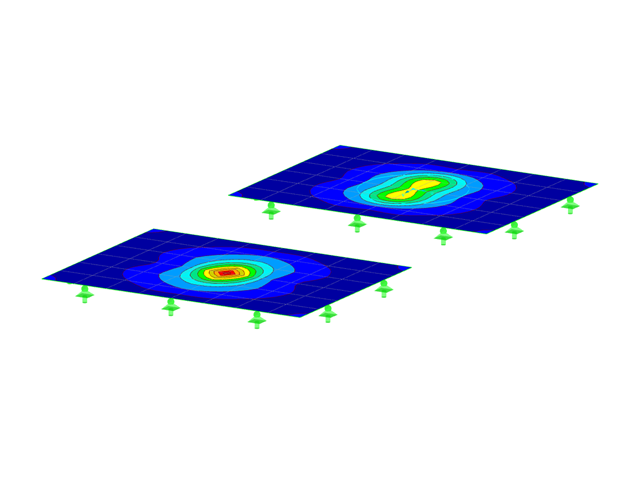
W artykule tym pokazano wpływ różnych sztywności ścian drewnianych na rzut.
Bei der Abbildung einer Rippe aus Stahlbeton mit darüberstehender Mauerwerkswand besteht die Gefahr einer Unterbemessung der Rippe, wenn das Tragverhalten des Mauerwerks nicht korrekt berücksichtigt und die Verbindung zwischen Mauerwerkswand und Unterzug nicht ausreichend genau modelliert wird. Dieser Artikel soll sich mit dieser Problematik und den möglichen Modellierungen einer solchen Konstruktion auseinandersetzen. Im Beispiel wird die Bewehrung rein aus den Schnittgrößen und ohne jegliche konstruktive Mindestbewehrung ermittelt.
Obliczenia paneli drewnianych są przeprowadzane na uproszczonych konstrukcjach prętowych lub powierzchniowych. W tym artykule opisano, jak określić wymaganą sztywność.
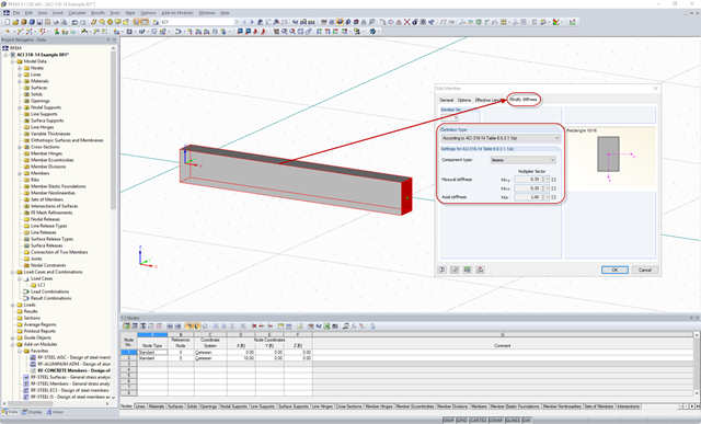
Zgodnie z rozdz. 6.6.3.1.1 i ust. 10.14.1.2 ACI 318-14 i CSA A23.3-14, program RFEM efektywnie uwzględnia redukcję sztywności prętów betonowych i powierzchni dla różnych typów elementów. Dostępne typy wyboru obejmują zarysowane i niezarysowane ściany, płaskie płyty, belki i słupy. Dostępne w programie mnożniki zaczerpnięto bezpośrednio z tabel 6.6.3.1.1(a) i 10.14.1.2.
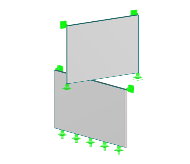
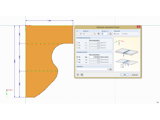
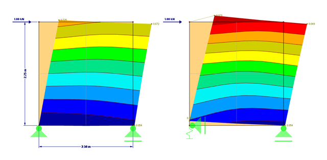
In diesem Beitrag geht es um die Ermittlung der Kontaktkraft zwischen zwei wandartigen Objekten, welche in einem gewissen Winkel schräg übereinander stehen. Zur Ermittlung dieser Kontaktkraft eignet sich die Definition einer Knotenfreigabe. Da eine Knotenfreigabe bestimmte Bedingungen voraussetzt, werden zwei Beispiele dargestellt.
Menadżer projektów jest instalowany domyślnie podczas instalacji programów RFEM oraz RSTAB i ułatwia zarządzanie wszystkimi projektami oraz plikami obliczeniowymi. W Menadżerze projektów można połączyć kilka różnych projektów, dzięki czemu użytkownik ma wygodny i przejrzysty podgląd plików programu. Obie metody mają różne cechy i mogą być mniej lub bardziej odpowiednie w zależności od okoliczności. W tym artykule przedstawiono przegląd dwóch metod obliczeniowych.
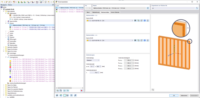
Usztywnienie konstrukcji drewnianych jest zwykle realizowane za pomocą drewnianych paneli. Hierfür werden plattenartige Werkstoffe (Grobspanplatten, OSB) mit Stäben verbunden. In mehreren Beiträgen werden die Grundlagen dieser Bauweise und die Berechnung im Programm RFEM erläutert. In diesem ersten Beitrag wird die grundlegende Ermittlung der Steifigkeiten sowie die Berechnung erläutert.
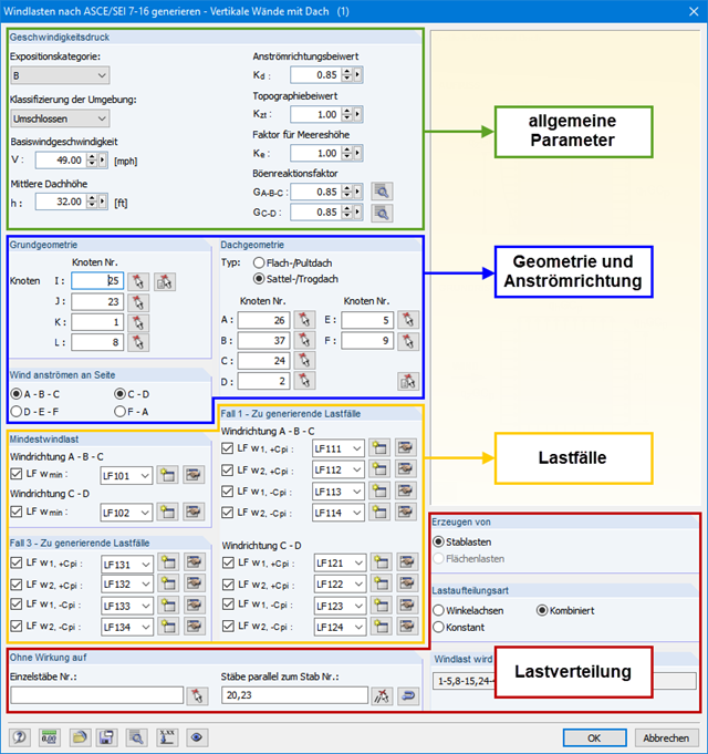
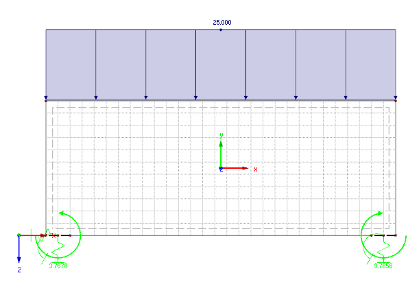
Programy RFEM i RSTAB umożliwiają łatwe uwzględnienie wpływu obciążenia wiatrem na budynek trójwymiarowy zgodnie z ASCE/SEI 7-16. W tym artykule wyjaśniono złożoną teorię wprowadzania obciążeń wiatrem do programu. Obciążenie wiatrem można znaleźć w "Narzędzia" → "Generować obciążenia" → "Od obciążeń wiatrem".
W przypadku konstrukcji płytowych zawsze należy uwzględnić realistyczne warunki podparcia definicji. Je nachdem, in welcher Art und Weise die Nachgiebigkeit der Lagerung definiert wird, ergeben sich zum Teil deutliche Unterschiede in den Ergebnissen.