_LI.jpg?mw=760&hash=08afe6762d6887a05b9da0069cb630169ffc359f)
The roller coaster has a length of 504 m (1,653.5 ft). Its seven roller coaster elements include three inversions. The X‑train has a capacity of 20 passengers. With top speeds of 56 mph, the train reaches up to 4.5 g (g‑force) several times.
Structural System
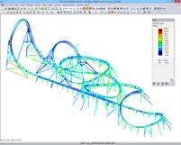
The base area is 113 m× 51 m (370.7 ft × 167.3 ft). At the highest point of the coaster ride, which is called the top hat, a vertex height of approximately 30 m (98 ft) is reached. The overall structure consists of a tubular structure with 6,201 members and 86 cross‑sections.
Structural Analysis
The rail structure was calculated in RSTAB. Both model and wheel loads were directly imported from the dynamic simulation using RS‑COM.
The analysis was performed according to Chinese and European standards. The analysis included ultimate limit state design and fatigue design.
The German engineers accessed the RSTAB results by using RS‑COM again for the fatigue designs. Then, the design according to EN 1993‑1‑9 and GB 50017 was carried out with post-processing programs.
RS-COM was used again to return the results of the post-processing programs to RSTAB in order to represent the results graphically on the rendering of the entire model.
| Structural Engineering | Structural Analysis and Fabrication Maurer Söhne GmbH & Co. KG, Munich www.maurer.eu |
| Investor | Romon U-Park Ningbo, China |