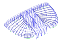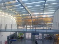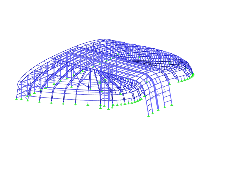
The building’s central portion is supported by two rows of centrally spaced columns on the left and the right to form an entryway that also serves as a glass atrium. The center roof is formed by two lateral Vierendeel trusses and a massive middle truss supported by the elevator shaft at the span center. The beams which support the glass panels are placed between the trusses. The beams and trusses further form a lattice structure.
The right and left parts of the building are also formed by Vierendeel trusses. At the structure base, the trusses frame into the concrete footing with a pinned connection. The roof interior is supported by the center lateral main trusses. These trusses are further supported by multiple columns with additional vertical bracing. At the building’s entrance, a pedestrian bridge is suspended from the steel roof members joining together the two outer portions of the structure.
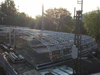
The rear wall at the platform side connects all parts of the building, forming the gable wall. This wall consists of columns and intermediate beams complete with an aluminum facade. Interior wall bracing also exists. The overhang extends the roof beyond the plane of this longitudinal wall.
The columns are pinned at the base, and at the top they are horizontally connected to a lattice truss formed by the gable beam upper chords and the first truss, with diagonal members spanning the chords. Around the building exterior, there are windows anchored directly to the horizontally spanning beams. The cladding includes load-bearing trapezoidal sheeting, an insulating layer, and standing seam sheets (Kalzip). In the areas with the greatest curvature, additional short struts are inserted between the Vierendeel trusses to ensure sufficient surface curvature for the trapezoidal sheet cladding.
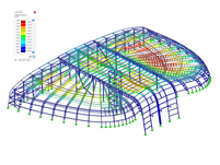
The Vierendeel trusses are comprised of round tube chords (steel S355) and vertical webs manufactured with sheet metal P12 (steel S235). The load-bearing trapezoidal sheeting, as well as the spacer elements throughout the roof, the horizontally spanning beams used to anchor the windows, and other elements used to transfer the vertical load tangential component to the cladding surface, prevent the upper chord from out-of-plane buckling. For the lower chord, both the upper chord’s elastic support through the vertical webs and the spacer elements connecting the beam’s lower chords contribute to prevent out-of-plane buckling.
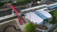
| Location | Karlovy Vary, Czech Republic |
| Structural Analysis | Ing. Jan Mařík, Ph.D. Ing. Jan Seifert |
| Architectural Design | PETR FRANTA architekti & asoc., spol. s.r.o. |