Cross-Section Classes
Eurocode 3 [1] defines four cross-section classes:

The cross-section classification provides the following parameters and boundary conditions:
- Support of a cross‑section part (on one or both sides)
- Length c of a cross‑section part
- Thickness t of a cross‑section part
- Yield strength of the steel used in the form of the factor ε
- Distribution of stresses on the designed cross‑section part
The class of the cross‑section part with the least favorable value governs for the entire cross‑section. For I-sections and H-sections, this is usually the comparatively slender web.
Stress Distribution
The stress distribution is detected by the parameter alpha (plastic, Class 1 and Class 2) or psi (elastic, Class 3). In this case, alpha represents the percentage length of the compression stress in the cross-section part while psi represents the ratio of the boundary stresses.

Important:
- The existing stresses are always calculated up or down to the yield strength.
- Compression stresses are always to be set as positive, tensile stresses as negative.
In solely uniaxial bending in a double symmetric cross-section, the determination of alpha and psi is trivial. An additional axial force requires further considerations. The interesting is, to what extent the normal force applies. There are two approaches and both are implemented in RF-/STEEL EC3.
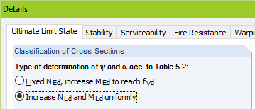
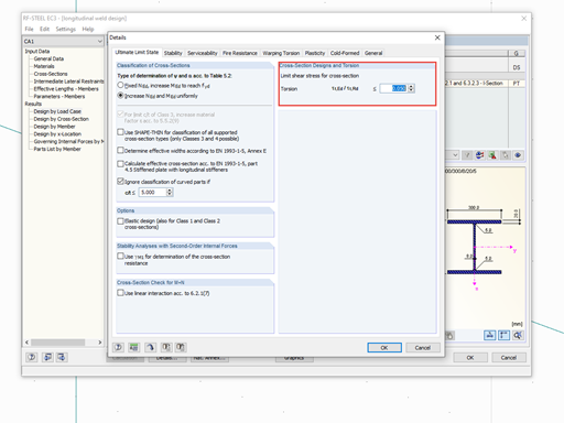
First, there is the second option "Increase NEd and MEd uniformly", which is preset in RF‑/STEEL EC3. In the case of the elastic stress distribution, the existing stresses are increased by the yield stress/largest compression stress ration in the cross-section part. The psi parameter results from the relation of compression stress and tension stress. If the stress distribution is plastic, the moment and axial force is increased until one of the interaction conditions specified in [1] is reached and thus the plastic limit state is reached. See the explanation in [2], pp. 13.
RF-/STEEL EC3 uses the interaction condition according to Formula 6.2 because it is easily traceable and valid for all types of cross-sections. The following graphic shows an example of IPE 360, S 235, with the following internal forces and plastic resistances:
My,Ed = 125.0 kNm NEd = 300.0 kN
My,Rd = 239.5 kNm NRd = 1,709.0 kN
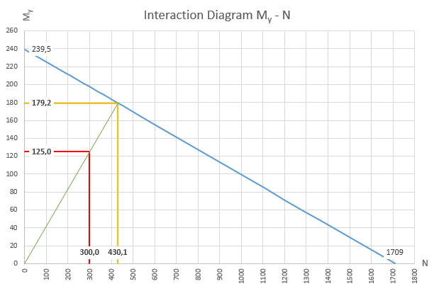
Extrapolation of the existing stresses results in the following limit internal forces:
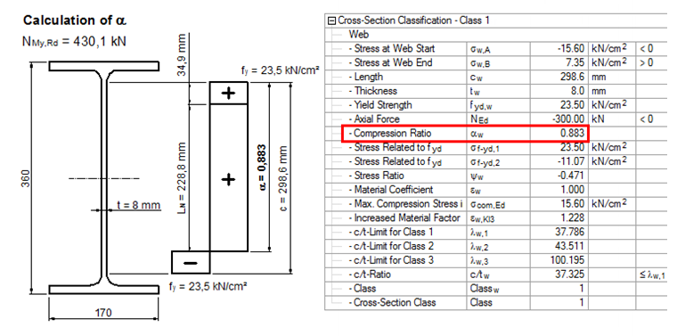
MN,y,Rd = 179.2 kNm NMy,Rd = 430.1 kN
On the basis of the limit axial force, the size of the stress block can be now determined and applied to in the area bisecting axes of the cross-section. By considering the remaining stress blocks of the bending moment, you can now determine the length of the compression stress in the cross-section part and thus the parameter alpha.
The first option, "Fixed NEd, increase MEd to reach fyd", can be explained easily on the plastic stress distribution. The axial force is not extrapolated, but rather applied to the acting size. As a result, the compression area and alpha are generally smaller when using this option.
The determination of c/t limit values for the individual cross-section classes are not further explained in this article. This information can be found in [1], Table 5.2.
References
[1]
EN 1993-1-1. (2009). Eurocode 3: Design of Steel Structures – Part 1-1: General Rules and Rules for Buildings, EN 1993-1-1:2005 + AC:2009.
[2]
SEMI-COMP+. (2011). Berechnungsrichtlinie für die Querschnitts- und Stabbemessung nach Eurocode 3 mit Schwerpunkt auf semi-kompakten Querschnitten. Graz, TU Graz – Institut für Stahlbau.


.png?mw=600&hash=49b6a289915d28aa461360f7308b092631b1446e)


