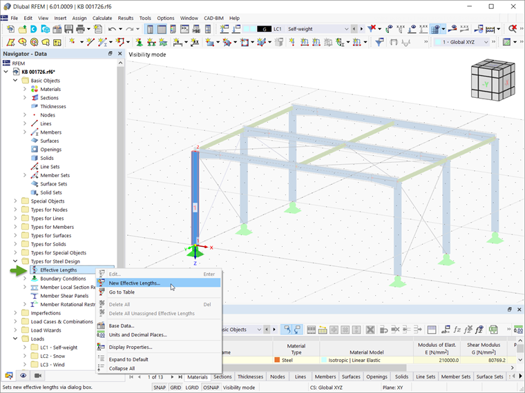
For buckling and lateral-torsional buckling analysis according to the equivalent member method, for example, according to EN 1993-1-1 [1] 6.3.1 to 6.3.3, it is necessary to define effective lengths in order to determine a critical load for the stability failure.
If an effective length has been assigned to a member or member set, the corresponding settings and effective lengths are taken into account in the stability analysis of the object. If there is no effective length defined, but the stability analysis is activated, a warning appears in the Errors & Warnings) table.
Main
In the Main tab, you can make basic specifications; in the Nodal Supports & Effective Lengths tab, you can then define the effective length factors and nodal supports. The input options are adjusted according to the standard that was selected in the Base Data of the model.

Considering Effective Lengths
Use the check boxes to specify which forms of stability failure are to be checked for the member or member set. Under compression, flexural buckling about the major or minor axis, as well as torsional buckling, can become governing. For unsymmetrical cross-sections with compressive loading, flexural-torsional buckling under pure compressive loading is also analyzed as a combination of flexural and torsional buckling. The "Lateral-torsional buckling" option activates the design for lateral-torsional buckling under bending.
Determination Type of Ideal Critical Moment
Depending on the selected design standard, there are various options for determining the critical lateral-torsional buckling moment Mcr (elastic critical moment). The eigenvalue method is preset. If you want to set the value manually, select the “User-defined” option. For some standards, there are additional options. For example, in the case of design according to AISC 360, the ideal critical moment can be determined according to Chapter F.
Buckling Axes
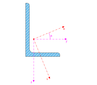
It is usually necessary to analyze the buckling behavior about the "principal section axes y/u and z/v". However, in the case of unsymmetrical cross-sections, it may be necessary to consider the flexural buckling about the "section axes y and z" in addition to the axes u and v. This special case is relevant, for example, for the design of angle sections in lattice towers.
Member Type
Standards like GB 50017 [2] differentiate between different structure types in a stability analysis. Depending on the selected standard, you can classify the member in this section, for example, as a cantilever or a beam supported on both sides.
Effective Length Factor Type
American design standards differentiate between the theoretical and the recommended values of the effective length factors. The effective length factors that can be defined as a template for members restrained on one side, for example, are adjusted according to the selection.
Options
The "Import from Stability Analysis" check box allows you to apply the effective length coefficients based on buckling modes. The corresponding entries can be specified in the additional tab Import from Stability Analysis.
Nodal Supports & Effective Lengths

Nodal Supports
Nodal supports on a member or a member set define the boundary conditions for the lateral-torsional buckling analysis. The nodal supports are also used to subdivide the member or the member set into segments.
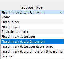
To define the supports, you can select common types from the list in the "Support Type" column. As an alternative, you can activate the check boxes in the individual cells (fixed supports), or deactivate them (no supports).
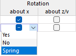
In addition to fixed or rigid supports, you can also define spring parameters for some directions. For this, use the cell shortcut menu. You can enter a spring stiffness in the Nodal Supports section.
Intermediate Supports
You can define the support conditions at the start, at the end, and at intermediate nodes. Standard nodes between members or a member set and nodes on members are considered as intermediate nodes (see the chapter Nodes of the RFEM manual).
The definition of intermediate nodes is not based on node numbers, but on the order on the member: .1 designates the first intermediate node from the member start, .2 the second one, and so on. If a member with this effective length has more or less intermediate nodes in the model then specified here, the consideration based on the member start applies and the excess entries or nodes are ignored.
To manually enter an intermediate node, select the "Intermediate node" check box. Using the
![]() button, you can then add new intermediate nodes. To delete an intermediate node, select the line and click the
button, you can then add new intermediate nodes. To delete an intermediate node, select the line and click the
![]() button. The table shortcut menu also provides the options for editing rows.
button. The table shortcut menu also provides the options for editing rows.
As an alternative, use the
![]() button to adopt the intermediate nodes of an object from the model. Select a member or a member set in the work window. The number of intermediate nodes is then transferred to the table.
button to adopt the intermediate nodes of an object from the model. Select a member or a member set in the work window. The number of intermediate nodes is then transferred to the table.
When the effective length is assigned to a member or a member set, you can check the assignment of nodes using the
![]() button. After you have selected a node in the work window, the row for the corresponding intermediate support is selected in the table (if defined).
button. After you have selected a node in the work window, the row for the corresponding intermediate support is selected in the table (if defined).
Once you have assigned the effective length to a member or member set, you can check the supports using the
![]() button in the dialog box's graphic (see the image Defining Nodal Support and Effective Lengths).
button in the dialog box's graphic (see the image Defining Nodal Support and Effective Lengths).
Effective Length Factors
The "Effective Length Factors" table is adjusted to the number of the nodal supports. If no intermediate nodes are defined, there is only one "segment". You can adjust the effective lengths of this segment to fit the boundary conditions by using the effective length factors to increase or reduce various failure modes.
Supports at the intermediate nodes subdivide the member or member set into segments for various failure cases:
- Support in z/v divides the length for buckling around the major axis by the ky/u factor.
- Support in y/u divides the length for buckling around the major axis by the kz/v factor.
- Restraint about x divides the length for torsional buckling by the kT factor.
An arrow in the column symbolizes an effective length factor across segments. This is the case when there is no intermediate support in the "Nodal Support" table.
You can define the effective length factors and thus adapt the effective lengths of a section by directly entering the factor or selecting one of the predefined values in the list of the cell shortcut menu.
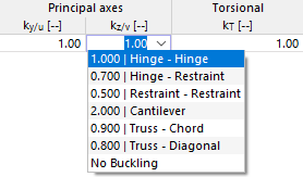
The effective length used for the design of a failure mode at a location in this segment results from the multiplication of the segment length by the corresponding effective length factor.
|
Lcr |
Effective length |
|
k |
Effective length factor |
|
L |
Member or segment length |
You can also specify the effective lengths directly. To do this, select the “Absolute values” check box. The column headings will then be changed to the length units.
For the lateral-torsional buckling design with the eigenvalue solver, each segment of the object with the corresponding supports is taken into account. The program determines the critical lateral-torsional buckling moment Mcr on an internal equivalent member model with 4 degrees of freedom (φx, φz, uy, ω) and the defined nodal supports. If you have selected the user-defined entry of Mcr, you can enter the value of the critical buckling moment for each segment manually. This value is then used for all design locations within the segment.
Nodal Supports – Additional Data
This section is displayed if a you have defined a spring as a nodal support or if there is a lateral support in y/u without a rigid restraint about x. You can define the parameters in detail here.

Enter the characteristic values of "springs" that are available for the lateral support or the rotation about the supported axes. You can also specify stiffnesses for warping springs.
The "Eccentricity" refers to the lateral support in y/u and, depending on the position of the compression flange, it can have a stabilizing or destabilizing effect for the lateral-torsional buckling. The list offers a support on an upper or a lower flange, as well as the option for defining it manually.
The spring stiffnesses and eccentricities are taken into account accordingly when determining the elastic critical moment for lateral-torsional buckling with the eigenvalue method.
Import from Stability Analysis
The Import from Stability Analysis tab is displayed if activating the corresponding check box in the Main tab. Here, you can select the buckling modes and members whose effective length factors ky/u or kz/v should be applied.
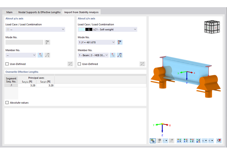
About Axis y/u / About Axis z/v
Specify the load cases of the stability analysis from which the effective lengths are to be imported. You can define a mode shape of a specific load case for each principal axis.
The mode shapes are properties of a load case or a load combination. First, select in the "Load Case / Load Combination" list, which load situation is governing for the buckling mode. The list only contains the load cases and load combinations with a specified stability analysis.
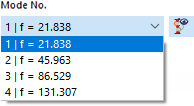
In the next step, define the governing "Mode No." The list of mode shapes is available for all calculated load cases and load combinations.
Click the
![]() button to display the mode shapes in the graphic window of the main program.
button to display the mode shapes in the graphic window of the main program.
Finally, select the "Member No." in the list. You can also use the
![]() button to define the member graphically in the work window.
button to define the member graphically in the work window.
Effective Length Factors
The table shows the effective length factors that were imported from the stability analysis for both principal axes. If you want to adjust the value manually, activate the "User-Defined" check box on top of the "About Axis" section. Thus, the text box becomes accessible.
The effective length factors displayed here are transferred to the Nodal Supports & Effective Lengths tab. They can no longer be edited there.
The "Absolute Values" option allows you to transfer the effective lengths Lcr,y/vcr,z/v of the members from the stability analysis results. You can use this option, for example, if you want to apply the effective length to a member set from a member included therein.