Seismic Configurations are currently available for steel design using the following standards:
- AISC 360
- CSA S16
These configurations control the criteria by which the seismic verification of an object is performed. Here you can define the seismic force-resisting system (SFRS) type for the seismic design according to AISC 341 [1] or CSA S16 [2].
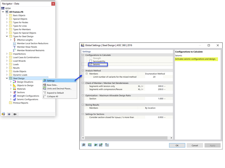
The seismic configuration can be activated in the Global Settings.
AISC 360

General
In this category, you define the seismic force-resisting system and member type.
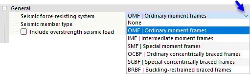
Seismic Force-Resisting System
Six types of seismic force-resisting systems (SFRS) are available in the list.
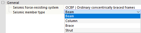
Member Type
Use the list to define the seismic member type. The options depend on which SFRS you have selected.
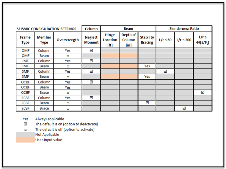
Various settings and inputs need to be considered depending on the SFRS type and member type selected for each configuration. These options are summarized in the table below. The member type “Strut” is reserved for multi-tiered braced frames (future release).
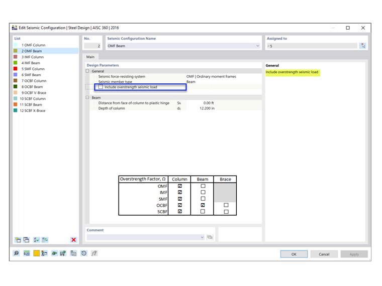
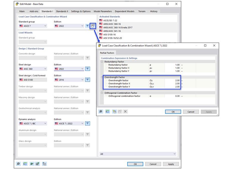
Include Overstrength Seismic Load
The overstrength factor, Ωo, is an amplification factor applied to the forces in certain elements in the seismic load path. The purpose is to prevent a weak link from occurring prior to the full energy dissipation and reaching the ductility potential of the primary SFRS. For example, in order for the diagonal brace in a steel braced frame to yield and dissipate energy in a controlled manner, all other elements of the load path (e.g., connections, columns, and collectors) need to be stronger than the maximum anticipated strength of the brace. Therefore, the design of those elements is based on the amplified loading using the overstrength factor.
When the “Include overstrength seismic load” box is selected, the overstrength factors are considered in the load combinations. As a result, the member is designed with the amplified loads. The columns are always required to be designed with the amplified loads and, therefore, the option to deactivate is not shown. The same is true for beams in OCBF.
Column Strength: Neglect Moments for Overstrength Limit State
All columns in a seismic force-resisting system (SFRS) are required to be designed with overstrength loads. In many cases, the amplified axial force does not need to be combined with the concurrent bending moments. The option to neglect all bending moments, shear, and torsion for the overstrength limit state of column type members is activated by default.
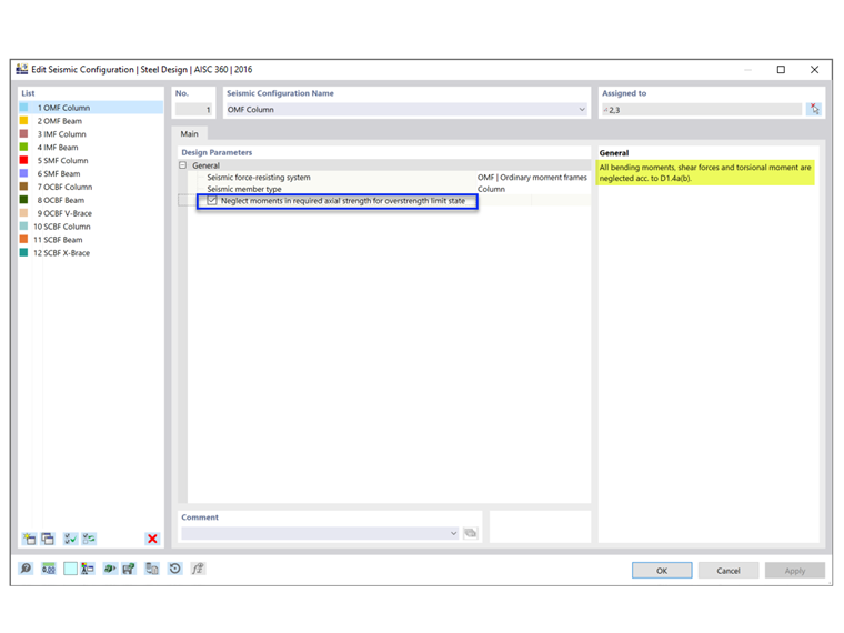
For standard load combinations without overstrength from seismic load effect, the combined loading according to AISC Chapter H is checked. For overstrength load combinations, the Chapter H check is ignored when the "Neglect moments" option is selected. Per AISC 341-16, both standard and overstrength load combinations must be checked. This is shown in Example 4.3.2 of the AISC Seismic Design Manual.
Beam / Column / Brace
The options of the second category depend on the seismic force-resisting system and member type selected above.
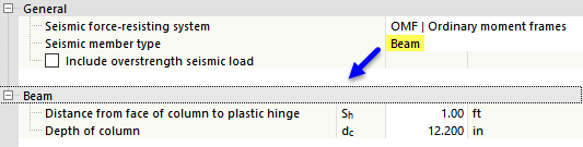
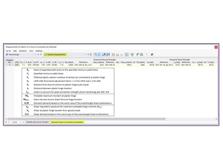
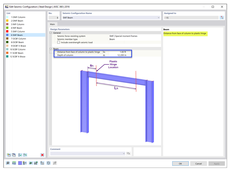
Distance from Face of Column to Plastic Hinge
The plastic hinge location, Sh, and the depth of the column, dc, are used to determine the required flexural and shear strength of the beam-to-column connection.
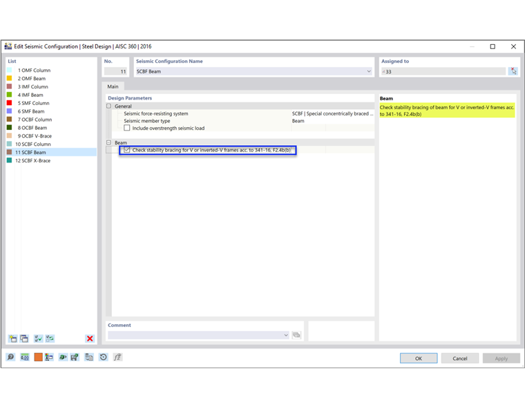
Check Stability Bracing for V-Frames
Stability bracing of beams is required for beams in IMF and SMF to restrain lateral-torsional buckling. In SCBF, this requirement is applicable to beams with V- or inverted-V-frames.
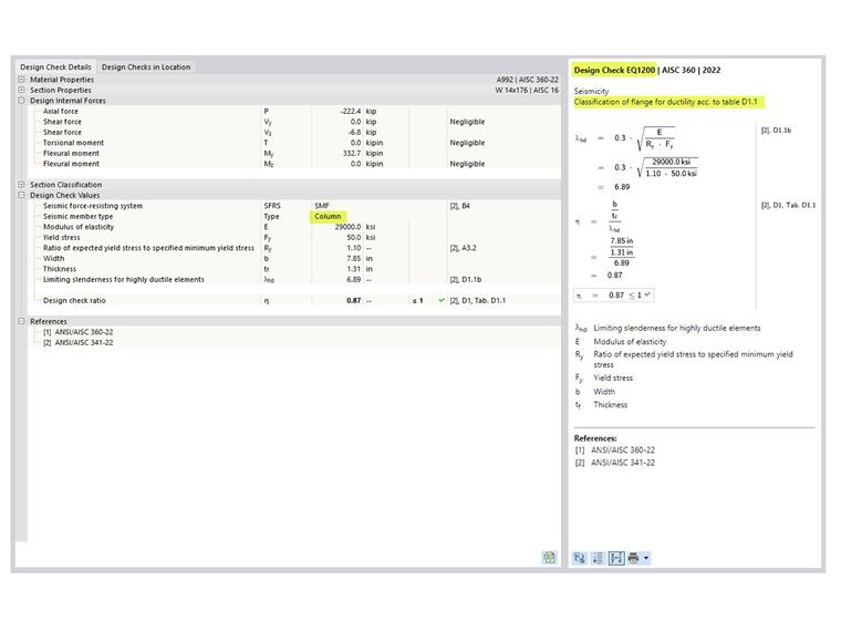
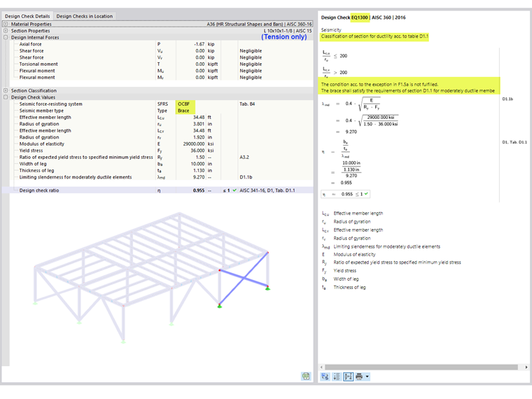
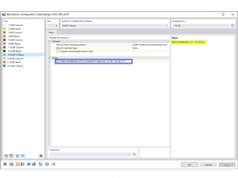
Check Slenderness
AISC 341 requires a more robust slenderness ratio for columns in SMF, braces with V- or inverted-V configuration in OCBF, and all braces in SCBF. The option to meet these requirements can be deactivated by the user.
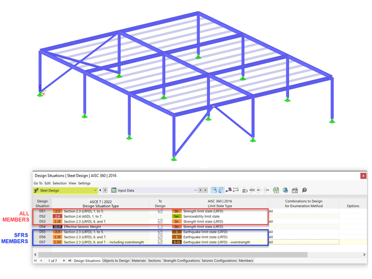
Design Situation Type & Limit State Type
The Design Situation Type that includes seismic load combinations needs to be added to consider the seismic loads. Careful attention must be given when applying the limit state type.
The AISC 341 seismic design is only performed when the Earthquake Limit State is selected in the Design Situations table as the limit state type. Only members with assigned Seismic Configuration are designed for all three limit state types: Strength, Earthquake, and Earthquake (overstrength). All other members that are not part of the SFRS are designed for the Strength Limit State.
The serviceability limit state is used to check for the deflection limit and can be deactivated by the user, if not needed.
CSA S16

General
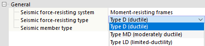
In this category, you define the seismic force-resisting system and type, and the seismic member type as set out in [2] Clause 27.
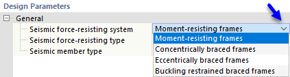
Seismic Force-Resisting System
There are four types of seismic force-resisting systems (SFRS) available in the list.
Seismic Force-Resisting Type
The seismic force-resisting types shown in the list depend on the selected SFRS.
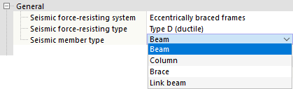
Member Type
Use the list to define the seismic member type. The options depend on which SFRS you have selected.
Bracing System
For concentrically braced frames, select the bracing system as well:
- Tension-compression
- Chevron
- Tension-only
Options
Various options and inputs need to be considered depending on the SFRS type and member type selected for each configuration. These options are described below.
Columns
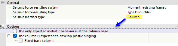
"The only expected inelastic behavior is at the column base" option is applicable for all SFRS of Column member types. It allows the column's Fy to be greater than 350 MPa, but less than or equal to 450 MPa per Clause 27.1.5.1 (as shown in design check EQ1100).
Moment-Resisting Frames
In most cases, plastic hinging is designed to occur in beams based on the Strong Column-Weak Beam (SCWB) philosophy. In specific cases where "The column is expected to develop plastic hinging", additional requirements according to Clause 27.2.3.1 must be satisfied. In the Steel Design add-on, the following requirements are verified:
- a) Design check EQ2200/3200: Column is laterally braced according to Clause 13.7(b) using k = 0.
- b) Design check EQ 2300/3300: Factored axial load ≤ 0.30AFy in SC4 for all seismic COs.
- d.1) Design check EQ1200: Column satisfies Class 1 limit in Table 2.
- d.2) Design check EQ 2400/3400: For "Fixed-base I-shaped column", h/w ≤ 700/√Fy unless the axial load Pf ≤ 0.15AFy (when Pf ≤ 0.15AFy, design check is not shown).
Concentrically Braced Frames
Per Clause 27.5.5.3 (b), columns in multistory buildings shall include an additional bending moment = 0.2ZFy in the direction of the braced bay, in combination with the computed bending moments and axial loads as shown in design check SP6400.
Eccentrically Braced Frames
Per Clause 27.7.13.2 (b), columns in multistory buildings shall include an additional bending moment = 0.2ZFy in the direction of the braced bay, in combination with the computed bending moments and axial loads. In the two top stories, Madd = 0.4ZFy as shown in design check SP6400.
Options for link beams
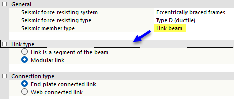
Per Clause 27.7.2.2, link beams shall be either
- a) a segment of the beam (I-section or built-up rectangular section), or
- b) a modular link with either
- end-plate connected link (I-shaped section) or
- web connected link (two built-up C-sections).
Design check EQ7100 verifies the section shape of link meets the above requirements based on the selected link type and connection type.
Option for beams
Per Clause 27.7.9.3, the beam outside the link shall be provided with lateral bracing at both the top and bottom flanges. If "Yielding is anticipated at the link end of this outer beam segment", the bracing shall also comply with Clause 13.7(a), which limits the lateral unsupported length, Lcr as shown in design check EQ7600.
Buckling Restrained Braced Frames
Per Clause 27.8.5.3 (b), columns in multistory buildings shall include an additional bending moment = 0.2ZFy in the direction of the braced bay, in combination with the computed bending moments and axial loads as shown in design check SP6400.
Design Situation Type & Limit State Type
The Design Situation Type that includes seismic load combinations needs to be added to consider the seismic loads. Careful attention must be given when applying the limit state type.
The seismic design according to Clause 27 is only performed when the Earthquake Limit State is selected in the Design Situations table as the limit state type. Only members with assigned Seismic Configuration are designed for both limit state types: Ultimate and Earthquake. All other members that are not part of the SFRS are designed for the Ultimate Limit State.
The serviceability limit state is used to check for the deflection limit based on the Serviceability Configurations.