


Local member cross-section reductions make it possible to take weakening of the cross-section such as bolt holes or cutouts into account in the design checks.

Type and Location of the Reduction
Reductions can be defined for various locations along the member or member set. Specify the appropriate number of lines by selecting the reduction type Design parameter in each case in the list.
Then enter the location x on the member or member set in each case. You can define the distance using either an absolute or a relative specification. With the
![]() button, you can switch between the two input options. If the weakenings are arranged at regular intervals, select the Multiple option. You can then define the number and offset in the Parameters | Design parameters section.
button, you can switch between the two input options. If the weakenings are arranged at regular intervals, select the Multiple option. You can then define the number and offset in the Parameters | Design parameters section.
The
![]() button offers the option of sorting the design parameters defined in the table in ascending order according to the location x.
button offers the option of sorting the design parameters defined in the table in ascending order according to the location x.
Parameters | Design Parameters
In this section, the design parameters for the selected location are defined. If multiple definition is selected, the number and spacing of the cross-section reductions are entered here. The distance can also be entered as absolute or relative.
The local cross-section weakening is entered by specifying the area reduction. After assigning the local cross-section reduction to an object, the net cross-sectional area is automatically calculated and displayed in the dialog from the gross cross-sectional area of the section at the relevant location minus the reduction area.
If no unique net cross-sectional area can be calculated due to assignment to several objects or several locations, the minimum and maximum values of the net cross-sectional areas are output in this dialog. For the check, the value corresponding to the location is used in each case.
If regulated in the selected design code, a factor for shear lag can also be defined (for example, for the single-leg connection of angle sections according to AISC).
For some design codes, provisions for the compression check can also be made; this is explicitly noted in the title of the option.
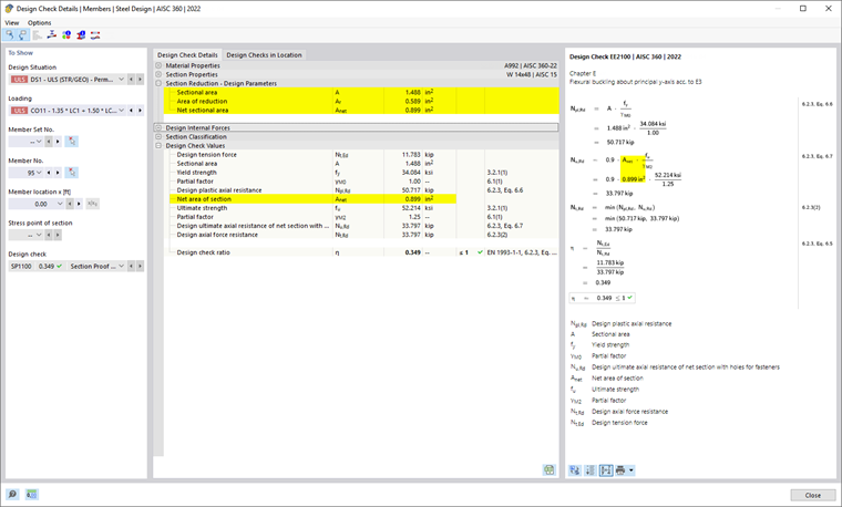
If a local member cross-section reduction has been considered in the design check, the corresponding intermediate values are output in the Design Details.
Graphical Display
In the Navigator - Display
![]() , you can activate the graphical display for Local Member Cross-Section Reductions including Bounding Lines in the Model → Steel Design category. For the members and member sets to which a member cross-section reduction is assigned, a cross-section outline is shown at the reduction locations.
, you can activate the graphical display for Local Member Cross-Section Reductions including Bounding Lines in the Model → Steel Design category. For the members and member sets to which a member cross-section reduction is assigned, a cross-section outline is shown at the reduction locations.