


For member design of 1D objects, you can use both Members and Member sets. While using members is usually sufficient for cross-section checks, member sets are often required for stability checks. This explains the significance of member sets for steel design.

Using member sets
In particular, for stability checks it is necessary to use a member set so that the critical load for the lateral-torsional buckling check is determined correctly or the entire member length is taken into account as the buckling length: For members, only the respective member length is considered. Therefore, as a rule, only a member-set-based check of the member is possible. The nodes between the members of a member set can be taken into account as intermediate nodes in the dialog box for Buckling Lengths or Boundary Conditions.
Straight, uniform members can alternatively be modeled as continuous members with Nodes on Members. The stability check is then also possible without member sets. However, some stability design methods can also design branched 2D systems as "one member", for example the General Method according to EN 1993-1-1 (see chapter Boundary Conditions). In this case, the use of member sets is mandatory.
Design members or member set
Members that are part of a member set can be designed either as a member or via the member set. To avoid contradictory input and results, when designing as a member set, the associated members are automatically deactivated for steel design. If you define the members for design, the superordinate member set is deactivated accordingly. You can check this rule in the input table Objects to Be Designed by listing the objects in the 'Not valid / deactivated' column.
After the design, a note is displayed in the results table Not valid / deactivated (see chapter Overview) for all members that were designed via a member set and thus deactivated. Likewise, member sets are marked there with a note if they were not designed.

Assign design properties
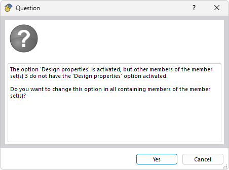
You can assign the same Design Specifications to a member set as to a member. Due to the restriction that a member set and a member can never be designed at the same time, after activating the design properties of a member in the member set, a query appears asking whether the remaining members should also be designed.
If you assign design properties to a member set, all members contained in it receive the design property Through superordinate member set and the design-relevant tabs of these members are hidden. Contradictory information is thus excluded.
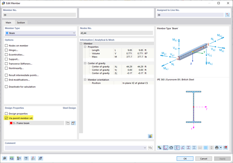
If no member set exists yet, you can create a new member set via the button
![]() in the 'Design Properties' section. With the button
in the 'Design Properties' section. With the button
![]() , you can edit the selected member set.
, you can edit the selected member set.