The essential boundary conditions for design checks are defined by assigning a type of steel design to an object to be designed. The assignment is done either by selecting members or member sets in the individual dialog boxes of the types, using the "Types for Steel Design" input tables, or by selecting a type for the steel design in the Design Properties of the object.
The design properties in the objects are accordingly available for the activated design add-ons, depending on the material. Members can be designed either as members or by using the superordinate member sets (see Chapter Member Sets). It is also possible to assign design properties by using representatives; this is described in Chapter Representatives.
Depending on the standard selected for the design, there are various types available for the steel design. The design standard is selected in the Base Data of the model; see Standards I. The description of the individual types can be found in the corresponding chapters of this manual.
- Effective Lengths
- Boundary Conditions
- Member Local Section Reductions
- Member Shear Panels
- Member Rotational Restraints
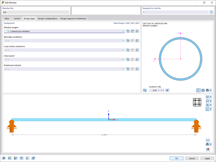
Select an existing type of the steel design from the list or use the
![]() button to create a new type. The
button to create a new type. The
![]() button allows you to graphically select another object, from which the respective type of steel design will be imported. Click the
button allows you to graphically select another object, from which the respective type of steel design will be imported. Click the
![]() button to open the edit menu of the selected type.
button to open the edit menu of the selected type.
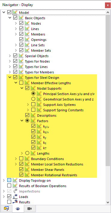
All types for the steel design can be displayed graphically in the work window. In the Navigator - Display, the corresponding display options can be found under the "Types for Steel Design" menu item. Thus, it is possible to easily check the correct assignment and to obtain clear documentation via the Graphic Printout.
The selected types for the steel design are also displayed in the lower part of the edit dialog box of the member or member set.