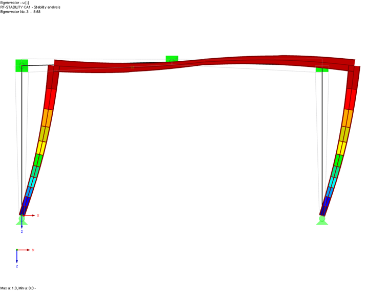
General Method for Stability Analysis
For buckling and lateral-torsional buckling analysis according to the general method in [1] 6.3.4, it is necessary to define boundary conditions so that the program can determine the critical load for stability failure. This method is an alternative to the equivalent member method according to Sections 6.3.1 to 6.3.3, which is based on the definition of effective lengths.
If a boundary condition is assigned to a member or member set, the specifications are taken into account in the stability design of the object. If an effective length is also assigned for the equivalent member design, the program displays an error message after the calculation, because there is no clear specification for the stability analysis (see also the Errors & Warnings result table). An error message also appears if neither effective lengths nor boundary conditions are assigned when the stability analysis is activated.
According to the standard specifications, the general method only analyzes the stability of structures for failure cases out of the main load-bearing plane, that is, lateral-torsional buckling, flexural buckling in the direction of the minor axis. If required, it is necessary to consider the flexural buckling in the main load-bearing plane when determining internal forces. This can be done using imperfections and a second-order analysis. The procedure for considering possible stability failure in the main load-bearing plane is described in a technical article (see on the right).
Main
The Main tab shows the definition type of the equivalent model and the coordinate system for entering nodal supports.
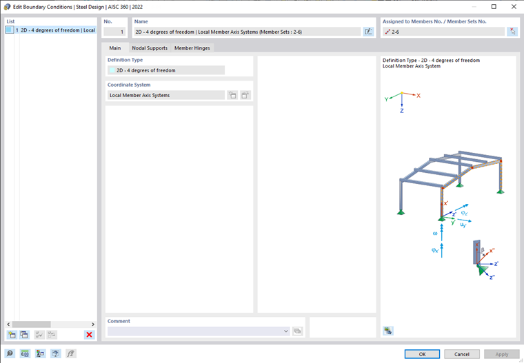
The program determines the critical load factor αcrit,op on an internal equivalent model with four degrees of freedom (φx, φz, uy, ω), fixed nodal supports, and member hinges. You can define the supports in the Nodal Supports tab and the hinges in the Member Hinges tab.
Nodal Supports

Nodal Supports
Using nodal supports, you can describe the supports of the object and thus set certain boundary conditions for the eigenvalue solver.
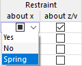
To define the supports, you can select common types from the list in the "Load Type" column. As an alternative, you can activate the check boxes in the cells of the individual columns (fixed supports), or deactivate them (no supports). You can also define spring parameters for each direction. For this, use the cell shortcut menu. The spring stiffness can be entered in the Additional Parameters section.
Intermediate Nodes
You can define the support conditions not only at the start and end of the object, but also at intermediate nodes. Standard nodes between members or a member set and nodes on members are considered as intermediate nodes (see the chapter Nodes of the RFEM manual). After the input, the numbers are specified in the "Nodes" column.
The definition of intermediate nodes is not based on node numbers, but on the order on the member: .1 designates the first intermediate node from the member start, .2 the second one, and so on. So if a member with the boundary condition assigned has more or less intermediate nodes in the model than specified here, it is considered based on the member start. Excessive entries or nodes are ignored.
To enter a new intermediate node manually, select the "Intermediate nodes" check box. Using the
![]() button, you can then add new intermediate nodes. To delete an intermediate node, select the line and click the
button, you can then add new intermediate nodes. To delete an intermediate node, select the line and click the
![]() button. The table shortcut menu also provides the options for editing rows.
button. The table shortcut menu also provides the options for editing rows.
As an alternative, you can use the
![]() button to transfer the intermediate nodes of an object from the model. Select a member or a member set from the work window. The number of intermediate node is then transferred to the table.
button to transfer the intermediate nodes of an object from the model. Select a member or a member set from the work window. The number of intermediate node is then transferred to the table.
If a boundary condition is assigned to a member or a member set, you can check the assignment of the nodes using the
![]() button. After selecting a node in the work window, the row of the associated intermediate support is selected (if defined).
button. After selecting a node in the work window, the row of the associated intermediate support is selected (if defined).
As soon as the boundary condition have been assigned to a member or member set, you can check the supports using the
![]() button in the dialog box graphic (see the image Defining Nodal Supports).
button in the dialog box graphic (see the image Defining Nodal Supports).
Additional Parameters
This section is displayed if selecting a row with an activated support in the table. You can define further parameters in detail here.

The rotation angle β allows for a “support rotation” in the x-z plane of the member set.
If there is a spring, you can specify the properties of the “springs” that are available for the lateral support or the rotation around the supported axes, or that describe the warping stiffness.
The "eccentricity" refers to the support in the direction of the x- and z-axis. Depending on the location of the compression flange, it can have a stabilizing or destabilizing effect on the lateral-torsional buckling. The list provides support on the upper or lower flange as well as the option of manual definition.
The spring stiffnesses and eccentricities are taken into account accordingly when determining the elastic critical moment for lateral-torsional buckling using the eigenvalue method.
Member Hinges
In the Member Hinges tab, you can define the individual member sections (segments) that you have specified in the Nodal Supports tab.

At the start and end of the segment, you can apply a hinge, thus enabling the displacement in y, the rotation about x and z, as well as the warping. For this, use the check boxes in the table. The directions refer to the coordinate system of the segment. The cell shortcut menu also allows you to use springs for the hinge stiffnesses. The spring properties can be entered in the "Additional Parameters" section (see the image above).