The Design Support and Deflection tab is available in the editing dialog box of a member or member set if the design properties of the object are activated (see the image Activating Design Properties of Member). Here you can define the object-related parameters that affect the design of local load introduction for cold-formed sections and the serviceability limit state design of the steel design.
You can make the specifications for the deflection analysis of surfaces in the Deflection tab of the surface editing dialog box.
Members

Design Supports
Design supports provide the option of segmenting the member or member set for the deflection analysis. You can assign these design supports not only to the member start and member end, but also to the inner nodes. In the table, both nodes of the “Node on Line/Member” type and standard nodes between members of a member set are set automatically.
Select a design support from the list or create a new type using the
![]() button (see the image New Design Support). Use the
button (see the image New Design Support). Use the
![]() button to change the selected type and the
button to change the selected type and the
![]() button to select an already assigned design support in the model.
button to select an already assigned design support in the model.

For hot-rolled steel sections, both the “General” design support type and the “Steel” type are suitable. If you use a design support for a member with a steel material, the “Steel” type is preset. The “Support width” or “Support depth” specifications are not relevant for the deflection analysis. If a design support is not to be taken into account for the segmentation, deactivate the “Active for deflection design” option.
If you want to perform the design of the local load introduction (local compression, web crippling, or local buckling in the web) for cold-formed sections according to EN 1993-1-3 [1] 6.1.7, AISI S100 [2], or CSA S136 [3], select the “Steel” design support type.
The "Support width" w defines the length of the stiff bearing sS. "Support depth" d, by contrast, has no influence on the design. The "support" is therefore not a bearing in the true sense of the word, but rather serves to describe the geometric parameters for taking the load into account.
Specify the effect of the support with the "Support from edge" list. The parameters +z and -z refer to the orientation of the local z-axis of the member. For example, if the load acts on the upper edge of the beam and the local z-axis points downwards, select the "-z/z'-axis" option. The load is thus assumed to be a compressive load for the section. With the "+z/z' axis" option, this would be a tensile load, as the load acts on the lower edge.
If there is an "End support", select the corresponding check box and define the "Overhang length" c. If the check box is cleared, the overhang length is considered to be infinite, so that c > 1.5 hw.
Deflection Analysis
Segments and Reference Lengths
In the right dialog section of the Design Supports and Deflection tab, you can find a list of the segments that result from the assignment of the design supports for the respective directions of the deflection analysis. For each design location in a segment, the displayed length Lc is used as the reference length for determining the limit value. If you want to change the automatically determined reference lengths, select the “User-defined lengths” check box. The values can then be edited. However, these user-defined lengths are not automatically adapted if you subsequently change the member length in the model.
Limit Values for Beams and Cantilevers
The deflection limit values for beams and cantilevers supported on both sides are managed in the Serviceability Configurations. The corresponding limit value is applied for each segment depending on the arrangement of the design supports during the design: A segment with design supports on both sides or with no design supports is regarded as a beam; a segment with a design support on one side is a cantilever.
Design Direction
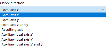
Use the “Design direction” to specify which result values of the deflection are to be checked. You can select the local axes y and z, the resulting deflection and the local auxiliary axes y' and z' from the list. The segments below adapt accordingly.
Displacement Reference
You can use the options in the “Displacement reference” list to influence the deflection values to be checked for the design:
- Undeformed system: The local deformation values uy and uz are taken directly from the results.
- Deformed segment ends: The deflection values are reduced by the deformation values of the start or end nodes for the design checks, so that only the local deflections are checked.
You can consider a "precamber" for each segment in the design and thus reduce the deflection value. The precamber is applied as a single-wave shape for beam segments and as a linear distribution for cantilever segments. Enter the precamber wc,z or wc,y as a positive value if it is opposite the local member axis z or y. To design the resulting direction, the precamber components are converted into the resulting direction.
Surfaces
In the ultimate limit state design of surfaces, the equivalent stresses are analyzed. The design checks are based on the material properties and surface thicknesses. For the serviceability design, however, surface-specific information is required. You can enter this data in the Deflection tab of the “Edit Surface” dialog box.

Surface Type
Use the surface type to specify which deflection limit values are used for the design. There are two options to select from in the list:
- Double-supported
- Cantilever
The limit values are stored in the Serviceability Configurations dialog box for various design situations for surfaces with support on both sides.
= Displacement Reference
The displacement reference controls which reference model is used for the design of deformations. The list contains three options:
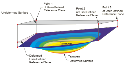
- Deformed user-defined reference plane: If the supports have very different displacements, you should enter an inclined reference plane for the displacement uz to be designed. Define the plane in the “User-defined reference plane” section by three points of the undeformed structural system. RFEM determines the deformation of the three definition points, defines the reference plane through these shifted points and uses the related maximum deformation uz for the design.
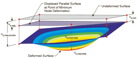
- Parallel surface at the point of minimum nodal deformation: This option is recommended if the support of the surface is yielding. The maximum deformation uz is related to a reference plane shifted parallel to the undeformed structural system, which RFEM places using the node with the smallest displacement value uz,min.
- Undeformed structural system: The local deformations uz are taken directly from the results and used for the design.
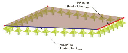
Reference Length and Definition Type
The limit value of the deflection depends on the reference length Lz. With the definition type options “By maximum boundary line” and “By minimum boundary line” (default setting), RFEM determines the length of the longest or shortest edge from the surface geometry and sets the reference length automatically. If you want to define the reference length, select the “Manually” definition type in the list and then enter the value.