


Member shear panels provide the option determine the lateral support of a member or member set using the components, such as bracing or trapezoidal sheeting. A member shear panel in y is taken into account when determining the elastic critical moment or the critical load factor for lateral-torsional buckling if this is determined by the internal eigenvalue solver. A constant translational spring is applied over the entire member or member set.

Definition Type
Several member shear panel types are available for selection in the list (see the image Dialog Box “New Member Shear Panel”).
Trapezoidal Sheeting
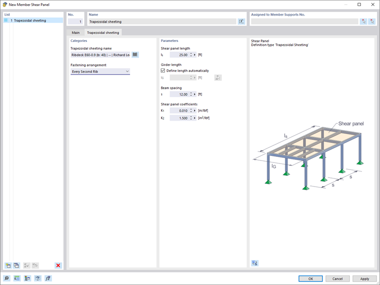
The following information is required to determine the shear panel stiffness of trapezoidal sheeting:
- Trapezoidal sheeting name
- Fastening arrangement
- Shear panel length
- Beam length
- Beam spacing
You can select the trapezoidal sheeting from a library using the
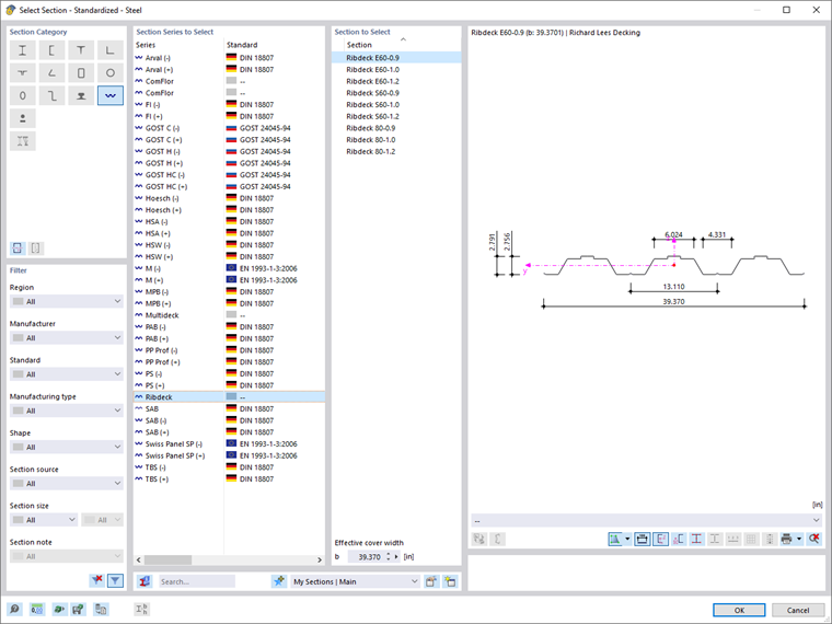
![]() button (see the image Cross-Section Library – Trapezoidal Sheeting). The shear panel coefficients K1 and K2 are automatically transferred, but can also be changed, if necessary.
button (see the image Cross-Section Library – Trapezoidal Sheeting). The shear panel coefficients K1 and K2 are automatically transferred, but can also be changed, if necessary.
The fastening arrangement for the trapezoidal section affects the shear stiffness that the sheeting provides to the beam. If the trapezoidal sheeting is fastened only in every second rib, the shear stiffness to be applied is reduced by the factor 5.
Enter the shear panel length and the beam spacing. You can also specify the dimensions graphically by selecting the "Measure" function using the
![]() button. Then, click on two snap points with the corresponding distance in the work window.
button. Then, click on two snap points with the corresponding distance in the work window.
The beam length is automatically adopted from the member or member set. Deactivate the "Define length automatically" check box if you want to specify the beam length manually.
Bracing
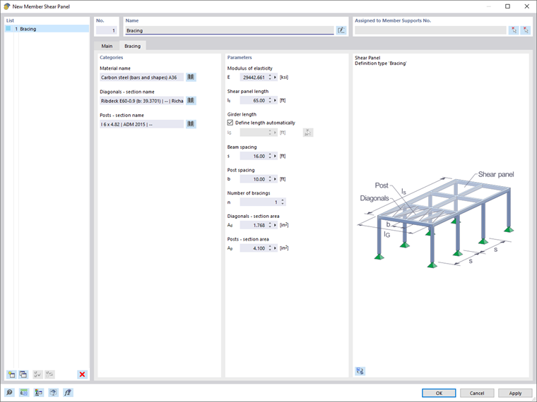
The following information is required to determine the shear panel stiffness of a bracing:
- Material name
- Diagonals – cross-section name
- Posts – cross-section name
- Shear panel length
- Beam length
- Beam spacing
- Post distance
- Number of bracing
You can select the material from the library by clicking the
![]() button (see the image Selecting Material in Library). The modulus of elasticity is automatically taken from the material, but can also be adjusted manually.
button (see the image Selecting Material in Library). The modulus of elasticity is automatically taken from the material, but can also be adjusted manually.
The easiest way to define the cross-sectional areas of the diagonals and posts is to select the cross-sections using the
![]() button in the Cross-Section Library. The cross-sectional area is automatically adopted. However, you can also enter the value directly.
button in the Cross-Section Library. The cross-sectional area is automatically adopted. However, you can also enter the value directly.
Enter the shear panel length, the beam spacing, and the post distance. You can also define the dimensions graphically by selecting the "Measure" function using the
![]() button. Then, click on two snap points with the corresponding distance in the work window.
button. Then, click on two snap points with the corresponding distance in the work window.
The beam length is automatically adopted from the member or member set. Deactivate the "Define length automatically" check box if you want to specify the beam length manually.
Furthermore, it is necessary to enter the number of bracing that stabilizes the roof level.
Trapezoidal Sheeting and Bracing
Use the "Trapezoidal Sheeting and Bracing" shear panel type to consider both trapezoidal sheeting and bracing as shear panels.
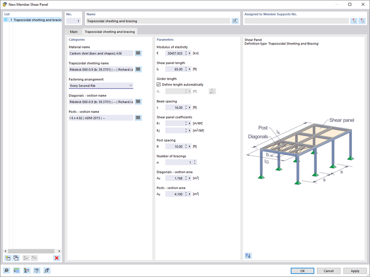
The following information is required to determine the shear panel stiffness:
- Material name
- Trapezoidal sheeting name
- Fastening arrangement
- Diagonals – cross-section name
- Posts – cross-section name
- Shear panel length
- Beam length
- Beam spacing
- Post distance
- Number of bracing
A description of the parameters can be found in the sections Sheeting Trapezoidal Sheeting and Bracing.
Defining S-prov
You can also specify the shear panel stiffness manually.
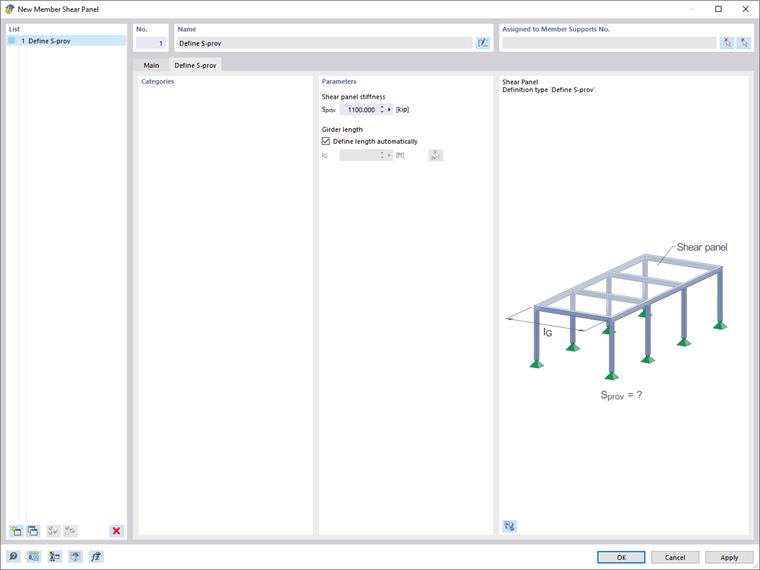
The following information is required for this:
- Shear panel stiffness
- Beam length
The beam length is automatically adopted from the member or member set. Deactivate the "Define length automatically" check box if you want to specify the beam length manually.
Assignment via Member Support
It is necessary to assign the member shear panel to a member or member set using a member-support. To do this, use the graphical selection option using the
![]() button (see the image Assigning Member Support) or use the member support dialog box. Select the Shear Panel in y or Shear Panel in z option in the “Nonlinearity / Fictitious Stiffnesses” list.
button (see the image Assigning Member Support) or use the member support dialog box. Select the Shear Panel in y or Shear Panel in z option in the “Nonlinearity / Fictitious Stiffnesses” list.
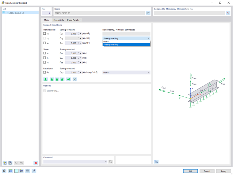
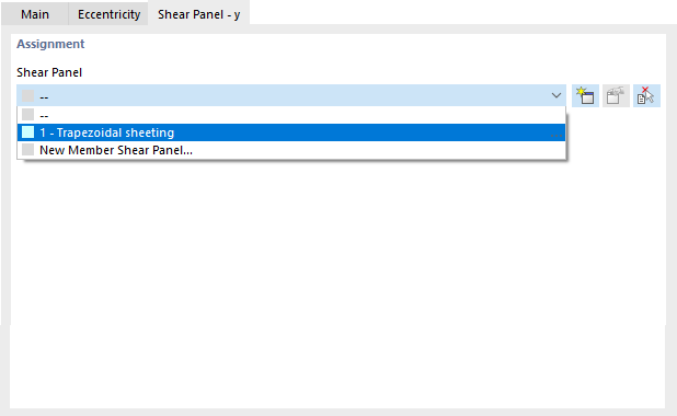
In the “Shear Panel - y” or “Shear Panel - z” tab, you can assign the relevant shear panel.
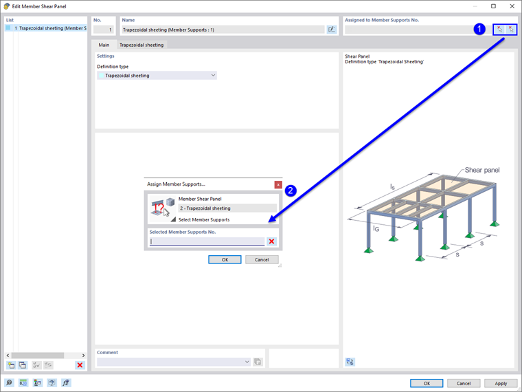
In the editing dialog box of the member shear panel, it is also possible to assign the shear panel to a member supportl graphically by clicking the
![]() button. However, there must already be a fictitious stiffness of the “Shear Panel” type for the member support.
button. However, there must already be a fictitious stiffness of the “Shear Panel” type for the member support.
Position of Shear Panel on Cross-Section
You can specify the position of the shear panel on the cross-section in the "Eccentricity" tab of the New Member Support dialog box.
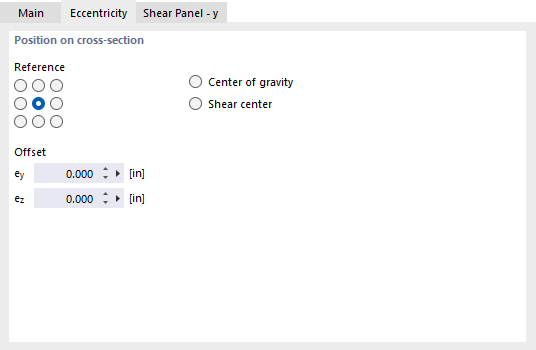
Nine "Reference" check boxes symbolize distinctive locations on the cross-section. The center point represents the centroid, and the eight edge points represent the intersection points of the member axes y and z with the edge lines of a rectangle circumscribing the cross-section. In addition, the center of gravity and the shear center are available as reference points.
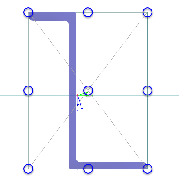
In the “Offset” input boxes, you can manually define the eccentricities ey and ez of the shear panel. The distances refer to the local member axes y and z. The shear panel is positioned on the cross-section using the distance defined as the offset to the selected reference point.