The entries in the Steel Design category in the navigator (see the image Categories for "Steel Design" in Navigator) and in the table (see the image Design Situations for Steel Design) control the basic assignments for the steel design. Here, you can specify the objects to be designed, check the object properties, such as materials and cross-sections, and assign the design configurations. The input data in tabular form also form the basis for the documentation in the printout report.
Using Input Tables

For the work in the input tables, you can use the functions known from RFEM. They are described in the chapter Tables of the RFEM manual.
You can use the
![]() button in the table toolbar or the shortcut menu in the “Steel Design” navigator entry to open the Global Settings dialog box, which manages the basic settings for the steel design.
button in the table toolbar or the shortcut menu in the “Steel Design” navigator entry to open the Global Settings dialog box, which manages the basic settings for the steel design.
Specific tables relating to the add-on are described in the following subchapters:
Use the
![]() button in the manu bars of the tables or the shortcut menu in the "Steel Design" navigator entry to open the Global Settings dialog box where you can control the basic specifications of the steel design.
button in the manu bars of the tables or the shortcut menu in the "Steel Design" navigator entry to open the Global Settings dialog box where you can control the basic specifications of the steel design.
Tables with functions that serve as “types” for design checks are described in the following subchapters:
Assigning Design Properties
For steel design, you can define several types with specific properties, which you can then assign to objects as design properties. However, it is also possible to create such object types when entering the design properties. This gives you the following options:
- In the type dialog boxes, enter the numbers of the relevant objects in the Assigned to section (see the [000101#image021184 New Effective Lengths] dialog box).
- Enter the numbers of the objects in the input tables of the types.
- Assign the type in the Design Types tab in the member or member set dialog box or define a new object type.


Select an already defined entry from the list (see the image Assigning Effective Length Type to Member). The
![]() button provides the option to create a new type. Using the
button provides the option to create a new type. Using the
![]() button, you can graphically select another object to adopt its properties for steel design. If you want to edit the selected entry, use the
button, you can graphically select another object to adopt its properties for steel design. If you want to edit the selected entry, use the
![]() button.
button.
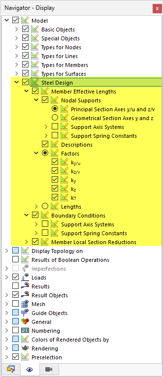
Displaying Parameters for Steel Design on Model
You can display the following design properties of members graphically on the model:
- Member effective lengths
- Boundary conditions
- Local member section reductions
You can find the corresponding display options in the category Model → Steel Design in the Navigator – Display. This allows you to easily check whether you have assigned the design properties correctly.
You can also use the Navigator options for the graphic printout.
Using Design Configurations
Detailed settings for the individual design checks are defined in "design configurations". For each limit state, there is a separate design configuration that manages the standard-specific regulations. Here, you can specify limit values or various design options, for example. Only those design configurations are available that are activated in the Global Settings dialog box for the selected standard.
- Ultimate Configurations
- Serviceability Configurations
- Fire Resistance Configurations
- Seismic Configurations
The design configurations are also organized as "types". You can create entries with different parameters for each configuration category. These types can then be assigned to the objects respectively, for example, in the Design Configurations tab of the "Edit Member" dialog box (see the image Assigning Design Configurations).
Assigning Design Configuration
The design configurations are organized as “types” (like the design properties): For each configuration category, you can create entries with different parameters. You then assign these types to the objects accordingly. You have the following options:
- Enter the numbers of the relevant objects in the Assigned to section of the dialog boxes for the individual configurations (see the [#image025532 Edit Ultimate Configuration] dialog box).
- Enter the numbers of the objects in the input tables of the Configurations (see the table Serviceability Configurations).
- Assign the configuration in the Design Configurations tab in the member, member set, or surface dialog box, or define a new configuration.

Select an already defined configuration from the list. The
![]() button allows you to create a new configuration. Use the
button allows you to create a new configuration. Use the
![]() button to graphically select another object, from which the respective configuration is adopted. If you want to edit the selected configuration, use the
button to graphically select another object, from which the respective configuration is adopted. If you want to edit the selected configuration, use the
![]() button.
button.

The list on the left shows all configurations that are defined for that limit state in the model. Use the
![]() button to create a new configuration, based on the default values of the standard. To copy an existing configuration, select it and click the
button to create a new configuration, based on the default values of the standard. To copy an existing configuration, select it and click the
![]() button. You can delete a configuration using the
button. You can delete a configuration using the
![]() button.
button.
If there is an object with no configuration assigned, no design checks are performed for this limit state. You can thus simply deactivate, for example, the serviceability limit state design for the individual members by not assigning the serviceability limit state configuration to these members.