28 Results
View Results:
Sort by:

Moment frame design according to AISC 341-16 is now possible in the Steel Design add-on of RFEM 6. The seismic design result is categorized into two sections: member requirements and connection requirements. This article covers the required strength of the connection. An example comparison of the results between RFEM and the AISC Seismic Design Manual [2] is presented.

Creating a validation example for Computational Fluid Dynamics (CFD) is a critical step in ensuring the accuracy and reliability of simulation results. This process involves comparing the outcomes of CFD simulations with experimental or analytical data from real-world scenarios. The objective is to establish that the CFD model can faithfully replicate the physical phenomena it is intended to simulate. This guide outlines the essential steps in developing a validation example for CFD simulation, from selecting a suitable physical scenario to analyzing and comparing the results. By meticulously following these steps, engineers and researchers can enhance the credibility of their CFD models, paving the way for their effective application in diverse fields such as aerodynamics, aerospace, and environmental studies.

Wind direction plays a crucial role in shaping the outcomes of Computational Fluid Dynamics (CFD) simulations and the structural design of buildings and infrastructures. It is a determining factor in assessing how wind forces interact with structures, influencing the distribution of wind pressures, and consequently, the structural responses. Understanding the impact of wind direction is essential for developing designs that can withstand varying wind forces, ensuring the safety and durability of structures. Simplified, the wind direction helps in fine-tuning CFD simulations and guiding structural design principles for optimal performance and resilience against wind-induced effects.

Both the determination of natural vibrations and the response spectrum analysis are always performed on a linear system. If nonlinearities exist in the system, they are linearized and thus not taken into account. They are caused by, for example, tension members, nonlinear supports, or nonlinear hinges. This article shows how you can handle them in a dynamic analysis.

Compliance with building codes, such as Eurocode, is essential to ensure the safety, structural integrity, and sustainability of buildings and structures. Computational Fluid Dynamics (CFD) plays a vital role in this process by simulating fluid behavior, optimizing designs, and helping architects and engineers meet Eurocode requirements related to wind load analysis, natural ventilation, fire safety, and energy efficiency. By integrating CFD into the design process, professionals can create safer, more efficient, and compliant buildings that meet the highest standards of construction and design in Europe.

To be able to evaluate the influence of local stability phenomena of slender structural components, RFEM 6 and RSTAB 9 provide you with the option of performing a linear critical load analysis on the cross-section level. The following article explains the basics of the calculation and the result interpretation.

The CSA S16:19 Stability Effects in Elastic Analysis method in Annex O.2 is an alternative option to the Simplified Stability Analysis Method in Clause 8.4.3. This article will describe the requirements of Annex O.2 and application in RFEM 6.

The size of the computational domain (wind tunnel size) is an important aspect of wind simulation that has a significant impact on the accuracy as well as the cost of CFD simulations.

The design of cold-formed steel members according to the AISI S100-16 is now available in RFEM 6. Design can be accessed by selecting “AISC 360” as the standard in the Steel Design add-on. “AISI S100” is then automatically selected for the cold-formed design (Image 01).

Windbreak structures are special types of fabric structures which protect the environment from harmful chemical particles, abate wind erosion, and help to maintain valuable sources. RFEM and RWIND are used for wind-structure analysis as one-way fluid-structure interaction (FSI).
This article demonstrates how to structural design windbreak structures using RFEM and RWIND.

This article discusses the options available for determining the nominal flexural strength, Mnlb for the limit state of local buckling when designing according to the 2020 Aluminum Design Manual.

The stability checks for the equivalent member design according to EN 1993-1-1, AISC 360, CSA S16, and other international standards require consideration of the design length (that is, the effective length of the members). In RFEM 6, it is possible to determine the effective length manually by assigning nodal supports and effective length factors or, on the other hand, by importing it from the stability analysis. Both options will be demonstrated in this article by determining the effective length of the framed column in Image 1.

Structure stability is not a new phenomenon when referring to steel design. The Canadian steel design standard CSA S16 and the most recent 2019 release are no exception. Detailed stability requirements can be addressed with either the Simplified Stability Analysis Method in Clause 8.4.3 or, new to the 2019 standard, the Stability Effects in Elastic Analysis method provided in Annex O.

- 000945
- Add-on Modules
- RF-FRAME-JOINT Pro 5
-
- JOINTS Steel | Column Base 8
- JOINTS Steel | DSTV 8
- JOINTS Steel | Pinned 8
- JOINTS Steel | Rigid 8
- JOINTS Steel | SIKLA 8
- JOINTS Steel | Tower 8
- JOINTS Timber | Steel to Timber 8
- JOINTS Timber | Timber to Timber 8
- RF-JOINTS Steel | SIKLA 5
- RF-JOINTS Steel | Column Base 5
- RF-JOINTS Steel | DSTV 5
- RF-JOINTS Steel | Pinned 5
- RF-JOINTS Steel | Rigid 5
- RF-JOINTS Steel | Tower 5
- RF-JOINTS Timber | Steel to Timber 5
- RF-JOINTS Timber | Timber to Timber 5
- FRAME-JOINT Pro 8
- Steel Structures
- Timber Structures
- Steel Connections
- Eurocode 3
- Eurocode 5
In addition to the result tables, you can create three-dimensional graphics in RF‑/FRAME‑JOINT Pro and RF‑/JOINTS. This is a realistic representation of a connection to scale.

When optimizing cross-sections in the add-on modules, you can also select arbitrarily defined cross-section favorites lists - in addition to the cross-sections from the same cross-section series as the original cross-section.

The elastic deformations of a structural component due to a load are based on Hooke's law, which describes a linear stress-strain relation. They are reversible: After the relief, the component returns to its original shape. However, plastic deformations lead to irreversible deformations. The plastic strains are usually considerably larger than the elastic deformations. For plastic stresses of ductile materials such as steel, yielding effects occur where the increase in deformation is accompanied by hardening. They lead to permanent deformations - and in extreme cases to the destruction of the structural component.

Describing the procedure for the serviceability limit state design of a floor slab made of steel fiber reinforced concrete. This article shows how to perform the corresponding design for the SLS by means of the iteratively determined FEA results.

Steel-fiber-reinforced concrete is mainly used nowadays for industrial floors or hall floors, foundation plates with low loads, basement walls, and basement floors. Since the publication in 2010 of the first guideline about steel-fiber-reinforced concrete by the German Committee for Reinforced Concrete (DAfStb), a structural engineer can use standards for the design of the steel fiber-reinforced concrete composite material, which makes the use of fiber-reinforced concrete increasingly popular in construction. This article describes the nonlinear calculation of a foundation plate made of steel fiber-reinforced concrete in the ultimate limit state with the FEA software RFEM.

When modeling a reinforced concrete rib with a masonry wall above, there is the risk that the rib is underdesigned if the structural behavior of the masonry is not correctly considered and the connection between the masonry wall and downstand beam is not modeled sufficiently accurately. This article deals with this issue and shows the possible modeling options of such a structure. In this example, the reinforcement is determined only from the internal forces and without secondary minimum reinforcement.

Determining the Material Properties of Steel-Fiber-Reinforced Concrete and Their Application in RFEM
Steel-fiber-reinforced concrete is mainly used nowadays for industrial floors or hall floors, foundation plates with low loads, basement walls, and basement floors. Since the publication in 2010 of the first guideline about steel-fiber-reinforced concrete by the German Committee for Reinforced Concrete (DAfStb), a structural engineer can use standards for the design of the steel fiber-reinforced concrete composite material, which makes the use of fiber-reinforced concrete increasingly popular in construction. This article explains the individual material parameters of steel-fiber-reinforced concrete and how to deal with these material parameters in the FEM program RFEM.

Different methods are available for calculating the deformation in the cracked state. RFEM provides an analytical method according to DIN EN 1992-1-1 7.4.3 and a physical-nonlinear analysis. Both methods have different features and can be more or less suitable depending on the circumstances. This article will give an overview of the two calculation methods.

For crane runways with large spans, the horizontal load from skewing is often relevant for the design. This article describes the origin of these forces and the correct input in CRANEWAY. The practical implementation and the theoretical background are discussed.
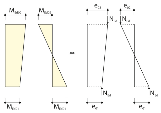
When calculating the internal forces for the buckling analysis with the method based on nominal curvature in RF‑CONCRETE Columns, the required eccentricities have to be determined.

- 001555
- Modeling | Loading
- RFEM 5
-
- RSTAB 8
- RF-TIMBER AWC 5
- TIMBER AWC 8
- RF-TIMBER CSA 5
- TIMBER CSA 8
- RF-TIMBER Pro 5
- TIMBER Pro 8
- RF-JOINTS Timber | Timber to Timber 5
- JOINTS Timber | Timber to Timber 8
- RF-JOINTS Timber | Steel to Timber 5
- JOINTS Timber | Steel to Timber 8
- RF-LIMITS 5
- LIMITS 8
- RF-LAMINATE 5
- Timber Structures
- Laminate and Sandwich Structures
- Structural Analysis & Design
- Finite Element Analysis
- Steel Connections
- Eurocode 0
- Eurocode 5
- ANSI/AISC 360
- SIA 260
- SIA 265
In addition to determining loads, some particularities concerning the load combinatorics in timber design have to be considered. Contrary to steel structures, where the largest loading results from all unfavorable actions, in timber construction, the strength values depend on the load duration and timber humidity. Special characteristics have to be considered as well for the serviceability limit state design. The following article discusses the effects on the design of wooden elements and how this is possible with RSTAB and RFEM.
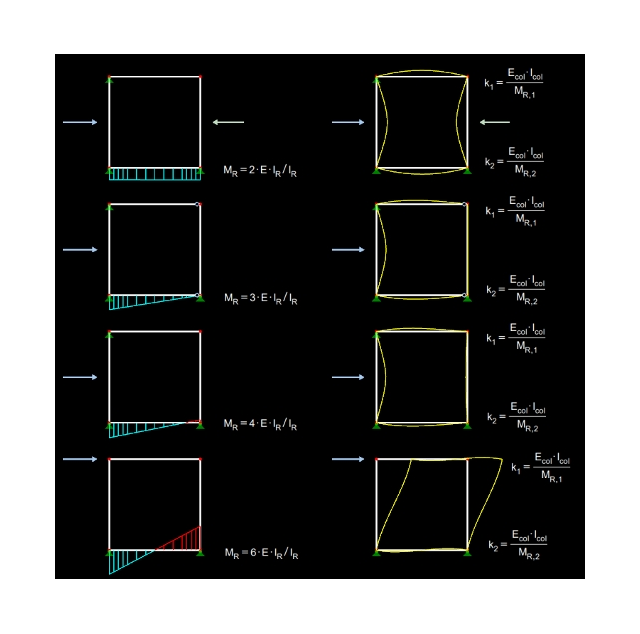
Effective lengths for columns can be determined automatically with RF-/CONCRETE Columns. This article describes which entries are necessary and how the calculation of the effective lengths is performed.

The design of a torsional loaded beam according to AISC Design Guide 9 will be shown, based on a verification example. The design will be performed with the RF‑STEEL AISC add-on module and the RF‑STEEL Warping Torsion module extension with 7 degrees of freedom.
When designing reinforced concrete components according to EN 1992‑1‑1 [1], nonlinear methods of determining internal forces for the ultimate and serviceability limit states are possible. In this case, the internal forces and deformations are determined with respect to their nonlinear behaviour. The analysis of stresses and strains in cracked state usually provides the deflections, which clearly exceed the linearly determined values.

After running an analysis in RF-/STEEL AISC, the mode shapes for sets of members can be viewed graphically in a separate window. Select the relevant set of members in the result window and click the [Mode Shapes] button.