38 Results
View Results:
Sort by:

To evaluate whether it is also necessary to consider the second-order analysis in a dynamic calculation, the sensitivity coefficient of interstory drift θ is provided in EN 1998‑1, Sections 2.2.2 and 4.4.2.2. It can be calculated and analyzed using RFEM 6 and RSTAB 9.

For the ultimate limit state design, EN 1998‑1, Sections 2.2.2 and 4.4.2.2 require a calculation considering the second‑order theory (P‑Δ effect). This effect may be neglected only if the interstory drift sensitivity coefficient θ is less than 0.1.

In order to be able to carry out a pushover analysis, it is necessary to transform the determined capacity curve into a simplified form. The N2 method is described in Eurocode EN 1998. This article should help to explain what a bilinearization according to the N2 method involves.

Both the determination of natural vibrations and the response spectrum analysis are always performed on a linear system. If nonlinearities exist in the system, they are linearized and thus not taken into account. They are caused by, for example, tension members, nonlinear supports, or nonlinear hinges. This article shows how you can handle them in a dynamic analysis.

The dynamic analysis in RFEM 6 and RSTAB 9 is divided into several add-ons. The Modal Analysis add-on is a prerequisite for all other dynamic add-ons, since it performs the natural vibration analysis for member, surface, and solid models.

Modal analysis is the starting point for the dynamic analysis of structural systems. You can use it to determine natural vibration values such as natural frequencies, mode shapes, modal masses, and effective modal mass factors. This outcome can be used for vibration design, and it can be used for further dynamic analyses (for example, loading by a response spectrum).

You can model and analyze masonry structures in RFEM 6 with the Masonry Design add-on that employs the finite element method for the design. Complex masonry structures can be modeled, and static and dynamic analysis can be performed, given that a nonlinear material model is implemented in the program to display the load-bearing behavior of masonry and the different failure mechanisms. You can enter and model masonry structures directly in RFEM 6 and combine the masonry material model with all common RFEM add-ons. In other words, you can design entire building models in connection with masonry.

Foundations including dimensions can be saved as a template in a user-defined database.

In RFEM 5 as well as RSTAB 8 in RF-/FOUNDATION Pro, you can save the foundation dimensions for all five foundation types as foundation templates in a user-defined database and use them later in other models.

In RF-/FOUNDATION Pro, the foundation design requires the definition of the corresponding loading (load cases, load combinations, or result combinations) for different design situations (STR, GEO, UPL, or EQU).

In RF‑/FOUNDATION Pro, reinforcement drawings are displayed after designing the foundation, where you can record all necessary structures of the reinforcement steel.

In RF‑/FOUNDATION Pro, the available reinforcing steel diameters can be adjusted by the user. The adjustment of the available rebar diameters works similarly to the same function in the RF‑/CONCRETE (Members) and RF‑/CONCRETE Columns add‑on modules.

In RF-/FOUNDATION Pro, the user can freely select the proportion of the relieving soil pressure by means of the factor kred.

In RF‑/FOUNDATION Pro, you now have the option to design a foundation at one or several nodes of the model.

In RFEM and RSTAB, different graphical representations of the foundation dimensions are available.

For foundation design, it is necessary to define the relevant loads for the respective design situations (STR, GEO, UPL, EQU).

When calculating foundations according to EC 7 or EC 2, different foundation types or sizes are usually used in one object. However, boundary conditions like the soil parameters, the materials for foundations, concrete covers, and the load combinations selected for design remain the same for all foundations, as a rule.

In RF-/FOUNDATION Pro, a graphical display of the result details is available. To see them, go to Window 2.2 Governing Design Criteria after the calculation. In the interactive graphic of this window, individual design-relevant values can be displayed for each design performed.

In RF-/FOUNDATION Pro, you can also consider the concrete cover for the foundation according to EN 1992-1-1.

RF-/DYNAM Pro - Equivalent Loads allows you to determine the loads due to equivalent seismic loads according to the multi‑modal response spectrum method. In the example shown here, this was done for a multi‑mass oscillator.

The response spectrum analysis is one of the most frequently used design methods in the case of earthquakes. This method has many advantages. The most important is the simplification: It simplifies the complexity of an earthquake to such an extent that an analysis can be carried out with reasonable effort. The disadvantage of this method is that a lot of information is lost due to this simplification. One way to mitigate this disadvantage is to use the equivalent linear combination when combining the modal responses. This article explains this option by describing an example.

Both the determination of natural vibrations and the response spectrum analysis are always performed on a linear system. If nonlinearities exist in the system, they are linearized and thus not taken into account. Straight tension members are very often used in practice. This article will show how you can display them approximately correctly in a dynamic analysis.

In order to consider inaccuracies regarding the position of masses in a response spectrum analysis, standards for seismic design specify rules that have to be applied in both the simplified and multi-modal response spectrum analyses. These rules describe the following general procedure: The story mass must be shifted by a certain eccentricity, which results in a torsional moment.

When introducing and transferring horizontal loads such as wind or seismic loads, increasing difficulties arise in 3D models. To avoid such issues, some standards (for example, ASCE 7, NBC) require the simplification of the model using diaphragms that distribute the horizontal loads to structural components transferring loads, but cannot transfer bending themselves (called "Diaphragm").

DIN EN 1998-1 with the National Annex DIN EN 1998-1/NA specifies how to determine seismic loads. The standard applies to structural engineering in seismic areas.

The RF-/FOUNDATION Pro add‑on module designs single foundations (foundation plates, bucket and block foundations) for all support forces arising in the RFEM/RSTAB model. The geotechnical designs are performed according to EN 1997-1.

In RF-DYNAM Pro - Equivalent Loads, the equivalent seismic loads can be calculated according to different standards. By calculating the equivalent loads for each eigenmode, it is not directly possible to obtain the transversal shear for each story to perform an analysis afterwards. The following example describes the option to calculate the transversal shear quickly and efficiently.
![Spectral Acceleration Sa [m/s²] Versus Natural Frequency f [Hz] of Narrow-Band Response Spectrum According to EN 1998-1 [1]](/en/webimage/009251/2417757/01-en-png.png?mw=640&hash=c76563b459152b19c98197ea6ba342be89d9a5bc)
In a multi-modal response spectrum analysis, it is important to determine a sufficient number of eigenvalues of the structure and to consider their dynamic responses. Regulations such as EN 1998‑1 [1] and other international standards require the activation of 90% of the structural mass. This means: to determine so many eigenvalues that the sum of the effective modal mass factors is greater than 0.9.
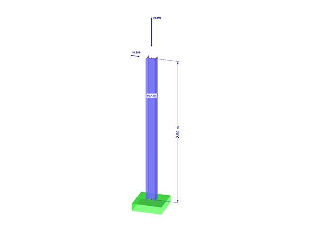
Using RF-/FOUNDATION Pro, it is possible to perform geotechnical design according to EN 1997-1 [1] for single foundations. The following article explains the design of highly eccentric loading in the foundation core according to DIN EN 1997‑1, A 6.6.5 (see [3]).
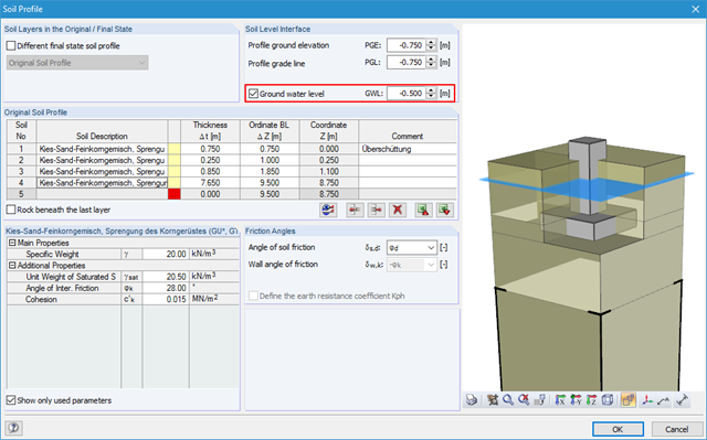
Using RF-/FOUNDATION Pro, it is possible to perform geotechnical design according to EN 1997‑1 [1] for single foundations. Subsequently, the program displays detailed information about the influence of the ground water level on the selected design according to EN 1997‑1.