42 Wyniki
Wyświetl wyniki:
Sortuj według:
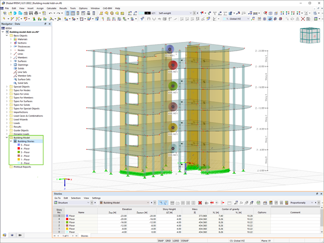
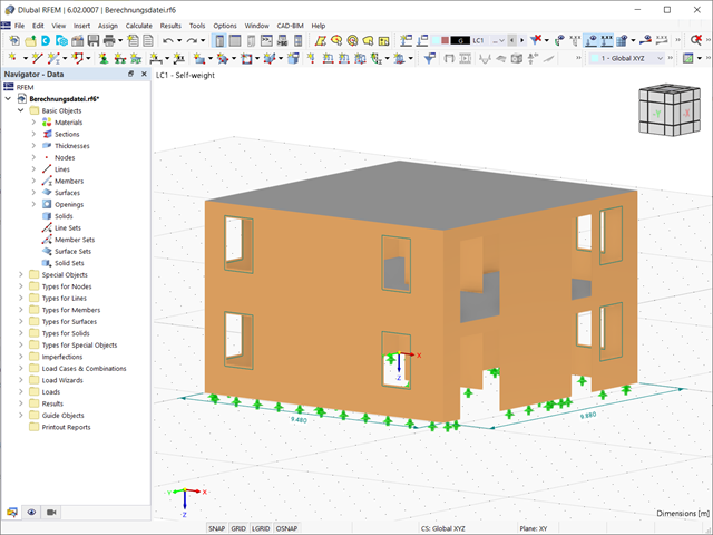
Model budynku jest jednym ze specjalnych rozszerzeń w programie RFEM 6. Jest to przydatne narzędzie do modelowania, za pomocą którego można łatwo tworzyć kondygnacje budynków i nimi manipulować. Model budynku można aktywować na początku procesu modelowania lub po jego zakończeniu.

Jedną z innowacji w programie RFEM 6 jest nowy sposób projektowania połączeń stalowych. W przeciwieństwie do programu RFEM 5, w którym wymiarowanie połączeń stalowych opiera się na rozwiązaniu analitycznym, rozszerzenie Połączenia stalowe w programie RFEM 6 oferuje rozwiązanie dla połączeń stalowych w oparciu o analizę MES.

Analiza sejsmiczna w programie RFEM 6 jest możliwa przy użyciu rozszerzeń analizy modalnej i analizy spektrum odpowiedzi. Ogólna koncepcja analizy sejsmicznej w programie RFEM 6 opiera się na utworzeniu przypadku obciążenia do analizy modalnej lub analizy spektrum odpowiedzi. Grupy norm dla tych analiz są ustawiane w zakładce Normy II w oknie Dane podstawowe modelu.
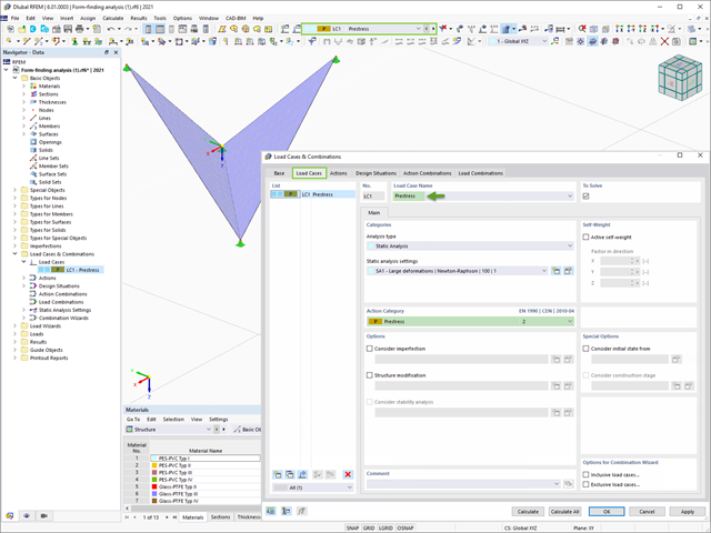
Program RFEM 6 zawiera rozszerzenie Form-Finding do określania kształtów równowagi modeli powierzchni obciążonych rozciąganiem i prętów obciążonych siłami osiowymi. Aktywuj ten dodatek w Danych bazowych modelu i użyj go, aby znaleźć położenie geometryczne, w którym naprężenie wstępne lekkich konstrukcji jest w równowadze z istniejącymi warunkami brzegowymi.

W tym artykule opisano, w jaki sposób płaska płyta budynku mieszkalnego jest modelowana w programie RFEM 6 i wymiarowana zgodnie z Eurokodem 2. Płyta ma grubość 24 cm i jest podparta na słupach o długości 45/45/300 cm w rozstawie co 6,75 m (rysunek 1). Słupy są modelowane jako sprężyste podpory węzłowe poprzez zdefiniowanie sztywności sprężystej na podstawie warunków brzegowych (rysunek 2). Jako materiały wybrano beton C35/45 i stal zbrojeniową B 500 S (A).

Obliczenia konstrukcji złożonych za pomocą oprogramowania do analizy elementów skończonych są zazwyczaj przeprowadzane na całym modelu. Jednak wznoszenie tego typu konstrukcji jest procesem wieloetapowym, w którym ostateczny stan konstrukcji uzyskuje się poprzez połączenie poszczególnych elementów konstrukcyjnych. Aby uniknąć błędów w obliczeniach ogólnych modeli, należy wziąć pod uwagę wpływ procesu konstrukcyjnego. W programie RFEM 6 jest to możliwe za pomocą rozszerzenia Analiza etapów budowy (CSA).
Obliczenia na przebicie zgodnie z EN 1992-1-1 należy przeprowadzić dla płyt poddanych obciążeniu skupionemu lub reakcji. Węzeł, w którym przeprowadzana jest analiza nośności na przebicie (tj. w miejscu, w którym występuje problem z przebiciem) nazywany jest węzłem odporności na przebicie. Obciążenie skupione w tych węzłach może zostać wprowadzone przez słupy, siłę skupioną lub podpory węzłowe. Koniec przyłożenia obciążenia liniowego na płyty również jest traktowany jako obciążenie skupione, dlatego należy również kontrolować nośność na ścinanie na końcach, narożach i końcach ścian oraz na końcach lub narożach obciążeń liniowych i podpór liniowych.

Zgodnie z EN 1992-1-1 [1] belka jest prętem, którego rozpiętość jest nie mniejsza niż 3-krotna całkowita wysokość przekroju. W przeciwnym razie element konstrukcyjny należy traktować jako belkę-ścianę. Zachowanie belek-ścian (tj. belek o rozpiętości mniejszej niż 3-krotna wysokość przekroju) różni się od zachowania belek-ścian (tj. belek o rozpiętości trzykrotnie większej niż wysokość przekroju).
Projektowanie belek-ścian jest jednak często konieczne podczas analizy elementów konstrukcyjnych konstrukcji żelbetowych, ponieważ są one wykorzystywane do budowy nadproży okiennych i drzwiowych, podciągów i podciągów, połączeń między płytami dwupoziomowymi oraz konstrukcji ramowych.
Projektowanie belek-ścian jest jednak często konieczne podczas analizy elementów konstrukcyjnych konstrukcji żelbetowych, ponieważ są one wykorzystywane do budowy nadproży okiennych i drzwiowych, podciągów i podciągów, połączeń między płytami dwupoziomowymi oraz konstrukcji ramowych.
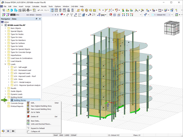
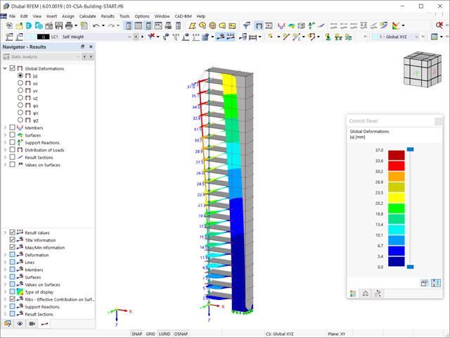
W programie RFEM 6 analizę sejsmiczną można przeprowadzić za pomocą modułów dodatkowych Analiza modalna i Analiza spektrum odpowiedzi. Zaraz po zakończeniu analizy spektralnej za pomocą rozszerzenia Model budynku można wyświetlić oddziaływania kondygnacji, przemieszczenia kondygnacji i siły w ścianach usztywniających.

Dzięki rozszerzeniu Połączenia stalowe dla RFEM 6 można tworzyć i analizować połączenia stalowe przy użyciu wydzielonego modelu ES. Modelowanie połączeń można kontrolować poprzez proste i wygodne wprowadzanie elementów. Elementy stalowego połączenia można definiować ręcznie lub przy użyciu szablonów dostępnych w bibliotece. Pierwsza metoda została opisana w poprzednim artykule z Bazy wiedzy zatytułowanym „Nowe podejście do wymiarowania połączeń stalowych w programie RFEM 6”. W tym artykule skupimy się na tej drugiej metodzie; tzn. pokaże, jak definiować komponenty połączenia stalowego przy użyciu szablonów dostępnych w bibliotece programu.

W programie RFEM 6 połączenia stalowe definiuje się jako układ elementów. W nowym rozszerzeniu Połączenia stalowe dostępne są podstawowe komponenty do uniwersalnego zastosowania (blachy, spoiny, płaszczyzny pomocnicze). Metody definiowania połączeń opisano w dwóch poprzednich artykułach w Bazie informacji: „Nowe podejście do wymiarowania połączeń stalowych w programie RFEM 6” oraz „Definiowanie elementów połączenia stalowego przy użyciu biblioteki” .

Zaletą modułu dodatkowego RFEM 6 Steel Joints jest możliwość analizy połączeń stalowych przy użyciu modelu MES, dla którego modelowanie przebiega w pełni automatycznie w tle. Elementy składowe złącza stalowego, które kontrolują modelowanie, można wprowadzić, definiując je ręcznie lub korzystając z dostępnych szablonów w bibliotece. Ta ostatnia metoda została opisana w poprzednim artykule z Bazy wiedzy zatytułowanym „Definiowanie komponentów połączenia stalowego przy użyciu biblioteki”. Definiowanie parametrów do wymiarowania połączeń stalowych jest tematem artykułu w bazie wiedzy „Projektowanie połączeń stalowych w RFEM 6”.
Rozszerzenie Analiza etapów budowy (CSA) umożliwia wymiarowanie konstrukcji prętowych, powierzchniowych i bryłowych w programie RFEM 6 z uwzględnieniem określonych etapów budowy związanych z procesem konstrukcyjnym. Jest to o tyle istotne, że budynki nie powstają w całości od razu, lecz poprzez stopniowe łączenie poszczególnych części konstrukcyjnych. Poszczególne kroki, w których elementy konstrukcyjne oraz obciążenia są dodawane do budynku, nazywane są etapami budowy, podczas gdy sam proces budowy nazywa się procesem konstrukcyjnym.

Rozszerzenie Wymiarowanie betonu umożliwia wymiarowanie słupów betonowych zgodnie z ACI 318-19. Poniższy artykuł potwierdzi wymiarowanie zbrojenia w rozszerzeniu Wymiarowanie betonu przy użyciu równań analitycznych krok po kroku zgodnie z normą ACI 318-19, w tym wymagane zbrojenie podłużne, pole przekroju brutto i rozmiar/rozstaw ściągu.

Jakość analizy statyczno-wytrzymałościowej budynków jest dużo lepsza, gdy można uwzględnić warunki gruntowe w sposób możliwie najbardziej realistyczny. W programie RFEM 6 można realistycznie określić kontur glebowy do analizy za pomocą rozszerzenia Analiza geotechniczna. Ten dodatek można aktywować w danych bazowych modelu, jak pokazano na rysunku 01.
Konstrukcje murowe można modelować i analizować w programie RFEM 6 za pomocą rozszerzenia Projektowanie konstrukcji murowych, który wykorzystuje do obliczeń metodę elementów skończonych. Zakładając, że w programie zaimplementowano nieliniowy model materiałowy, można modelować złożone konstrukcje murowe oraz przeprowadzać analizę statyczną i dynamiczną, aby przedstawić nośność konstrukcji murowej oraz różne mechanizmy uszkodzenia. Istnieje możliwość wprowadzania i modelowania konstrukcji murowych bezpośrednio w programie RFEM 6 oraz łączenia modelu materiałowego muru ze wszystkimi popularnymi rozszerzeniami dla programu RFEM. Umożliwia to projektowanie całych modeli budynków w połączeniu z murem.

Analiza modalna jest punktem wyjścia do analizy dynamicznej układów konstrukcyjnych. Można ją wykorzystać do określenia wartości drgań własnych, takich jak częstotliwości drgań własnych, kształty drgań własnych, masy modalne i efektywne współczynniki masy modalnej. Wynik ten może zostać wykorzystany do obliczeń drgań oraz do dalszych analiz dynamicznych (na przykład obciążenia widmem odpowiedzi).

Analiza dynamiczna w RFEM 6 i RSTAB 9 jest podzielona na kilka rozszerzeń. Rozszerzenie Analiza modalna jest niezbędne dla wszystkich innych rozszerzeń do analizy dynamicznej, ponieważ przeprowadza analizę drgań własnych dla modeli prętów, powierzchni i brył.
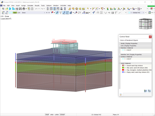
Biorąc pod uwagę, że realistyczne określenie warunków gruntowych znacząco wpływa na jakość analizy statyczno-wytrzymałościowej budynków, w programie RFEM 6 dostępne jest rozszerzenie Analiza geotechniczna, które umożliwia określenie konturu glebowego do analizy.
Sposób udostępnienia danych uzyskanych z badań polowych w rozszerzeniu i wykorzystania właściwości z próbek gruntu do określenia masywów gruntu, które mają być przedmiotem zainteresowania, został omówiony w artykule z Bazy informacji „Tworzenie bryły gruntowej na podstawie próbek gruntu w programie RFEM 6”. W tym artykule omówiono natomiast procedurę obliczania osiadań i parcia gruntu dla budynku żelbetowego.
Sposób udostępnienia danych uzyskanych z badań polowych w rozszerzeniu i wykorzystania właściwości z próbek gruntu do określenia masywów gruntu, które mają być przedmiotem zainteresowania, został omówiony w artykule z Bazy informacji „Tworzenie bryły gruntowej na podstawie próbek gruntu w programie RFEM 6”. W tym artykule omówiono natomiast procedurę obliczania osiadań i parcia gruntu dla budynku żelbetowego.
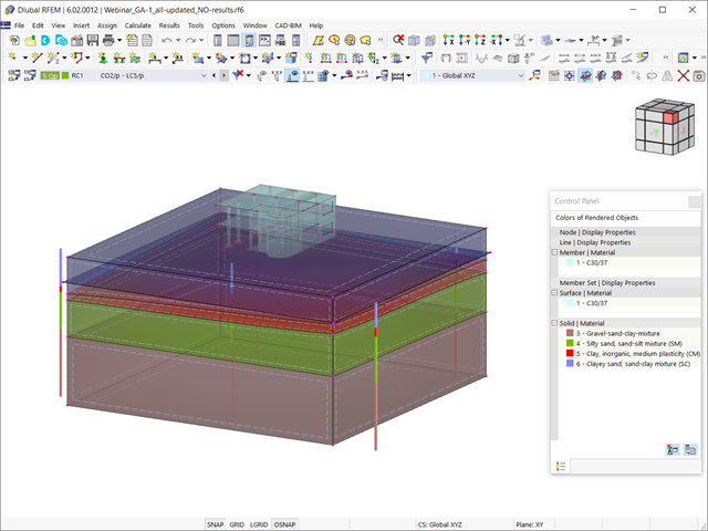
W tym artykule omówiono wyniki analizy geotechnicznej oraz ich graficzne i tabelaryczne przedstawienie w programie RFEM 6.