


The TNF tower was built in the 1970s and is the tallest building on the JKU campus, with a height of 164 ft. The slender Somnium steel structure was built on the roof of the existing building. The new observation platform is spatially framed by a lattice framework and offers an optimal view over the university campus and the surrounding city area.
Bollinger and Grohmann ZT GmbH from Vienna, Austria was commissioned with the structural analysis of the existing structure and the design of the Somnium. They utilized RFEM for the calculations.
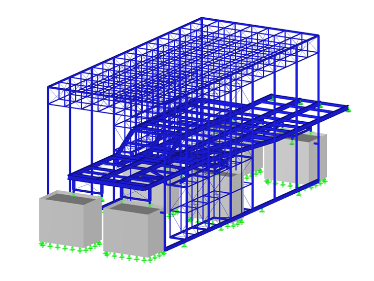
Structure
The steel structure has dimensions of approximately 154 ft L x 49 ft W x 56 ft H. The platform structure consists of primary and secondary beams made of standard rolled sections. Due to the large longitudinal expansion resulting from temperature changes, it rests on the existing shafts and the extended staircase without restraints. The existing shaft attics had to be partially replaced by new, highly reinforced concrete gratings in order to distribute the concentrated loads as much as possible into the existing structure. The platform structure was designed as a rigid plate in order to transfer the horizontal loads from the latticework to the gratings.
The main supporting structure of the lattice framework consists of square tube sections and tension members. In order to determine the optimal structural option, various stiffening concepts were analyzed. They were discussed between Bollinger+Grohmann and Riepl Riepl Architekten. Finally, it was decided to design the roof as a spatial framework partially supported in the vertical and horizontal directions. This design as a rigid truss frame ensures horizontal stiffening. The columns are connected to the platform structure at a height of about 20 ft above the roofline.
The plan is to have climbing plants grow on the side of the structure surfaces. For this purpose, climbing cables were arranged along the structure at distances of 2 ft. The planning and design of these cables was a particular challenge for the structural design. On one hand, the normal forces in the climbing ropes as well as the allowable horizontal deflection of the tension cables had to be carefully considered and controlled. On the other hand, the timber weight and realistic wind load approaches had to be determined.
Due to the additional vertical loads and the horizontal wind forces from the new steel structure, the existing structure also had to be analyzed. This was facilitated by examining the extensive plan documents from 1973/1974. The result of the investigations was the necessary reinforcement measures. For example, four ventilation shafts, which were originally separated from the building, were connected to the main wing by means of steel flaps on the eleventh floor. In addition, CFRP lamellas were glued to the shafts on the first and second floors.
Due to the close working relationship between Bollinger+Grohmann and Riepl Riepl Architekten, it was possible to create a very successful spatial supporting structure meeting both architectural and structural design requirements.
| Location | JKU - Johannes Kepler University Linz Altenbergerstrasse 69 4040 Linz, Austria |
| Owner | BIG Bundesimmobiliengesellschaft m.b.H. Vienna, Austria www.big.at |
| Architect | RIEPL RIEPL ARCHITEKTEN Linz, Austria www.rieplriepl.com |
| Structural Design | Bollinger and Grohmann ZT GmbH Vienna, Austria www.bollinger-grohmann.com |


