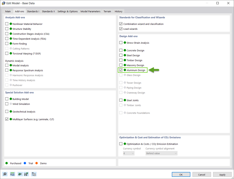
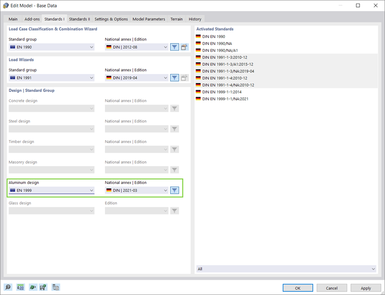
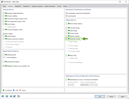
You can activate the Aluminum Design add-on in the Add-ons tab of the Base Data window, whereas you can set the preferred standard in the Standard I tab, as shown in Images 1 and 2.
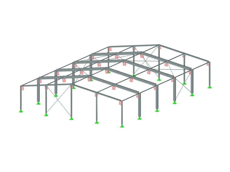
You can model aluminum structures using the relevant materials in the RFEM 6 material library. You can also define materials and add them to the library. However, it is important that the data specified in terms of materials, as well as in terms of load and result combinations, comply with the design concept of the standard. When designing according to European Standards, you should consider the following documents:
- Basis for Structural Design (Eurocode 0), to obtain the partial safety factors for loads and the rules for the combination thereof
- Actions on Structures (Eurocode 1), to consider loads relevant for the structures and buildings to be designed
- Design of Aluminum Structures (Eurocode 9), to apply the design rules for aluminum structures
You can create load and result combinations in RFEM automatically, in accordance with the standard, or manually. Either way, you can apply the loads by using the common load application procedure in RFEM.
Design Properties
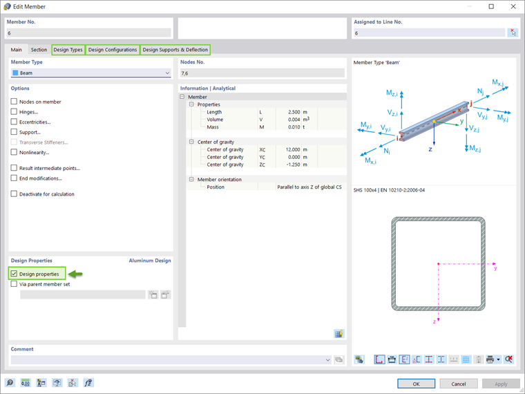
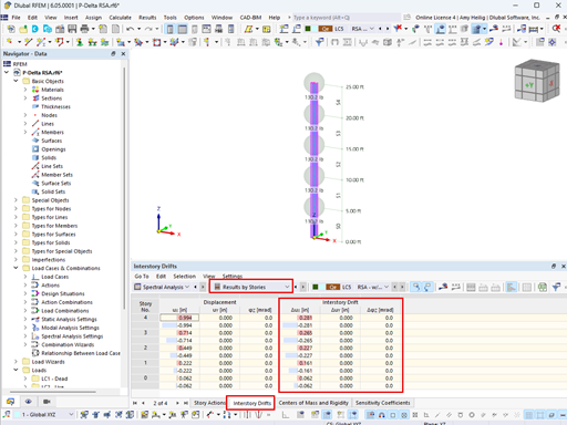
Once you have modeled the structure, applied the loads, and created the load and result combinations, you have to activate the design properties of the member or member set to be designed (Image 3). This will allow you to define the design types for the aluminum design, design configurations, and design supports necessary for the design procedure. The same applies for members or member sets designed through representatives.
Design Types
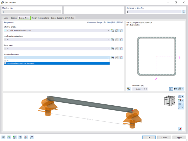
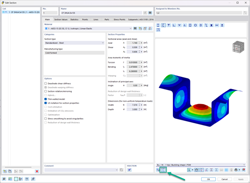
The aluminum design types include the definition of effective lengths, local section reductions (considered in tension design only), shear panels, and rotational restraints (Image 4). Defining the buckling lengths is necessary for determining the critical load for stability failure. After you assign a buckling length to an object of interest, the settings and effective lengths are taken into account in the stability design. Next in the design, you can consider local cross-sectional weakening (for example, screw holes) related to the object by assigning a local member cross-section reduction in the relevant window.
You can also define trapezoidal sheeting, bracing, trapezoidal sheeting and bracing, or shear panel stiffness (Sprov) and assign them to members. In a similar manner, you can apply a member rotational restraint with the stiffness type "Continuous”, “Discrete”, or “Manual” over an entire member or set of members and take it into account when determining the critical lateral-torsional buckling moment or the critical load factor for lateral-torsional buckling.
Design Configurations
You can access Design Configurations either through the Edit Member window, or through the Input Data of the Aluminum Design table. The specifications within a design configuration apply to all objects to which the configuration is assigned. If no design configuration is assigned to an object to be designed, no ultimate limit state or serviceability designs are performed for this object.
The Eurocodes suggest calculations to be carried out for two limit states: ultimate limit state and serviceability limit state. The former refers to a situation where the safety of the structure is checked so that structural collapse and failure are avoided, whereas the latter refers to certain requirements for the normal use of structures. For aluminum structures, these include requirements on deflection and, in certain circumstances, vibration. Due to aluminum’s low modulus of elasticity, this limit state is, in general, the critical design situation for aluminum structures.
Ultimate Design Configuration
You can create an ultimate configuration by defining various settings that affect the aluminum design (Image 5). For instance, you can define whether stability design checks are performed in addition to the cross-section designs, as well as adjusting further settings related to it. Next, the Limit Values for Special Cases option is available to allow you to neglect certain internal forces in the design that are unimportant for the load-bearing capacity. If you do not use this option, specific designs might be prevented or the use of more unfavorable interaction formulas might be implied.
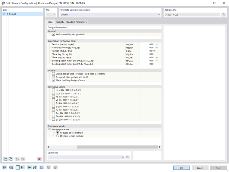
Depending on the design standard you select, other options such as activating an elastic cross-section design, alternative values for form factors and exponents in interaction formulas, or further detail settings for the local buckling or shear buckling design are available in the ultimate limit state configuration. For the design standard EN 1999, you can find the relevant coefficients according to the selected National Annex in the Standard Parameters of the window, but you can also adjust them with a user-defined value.
Serviceability Design Configuration
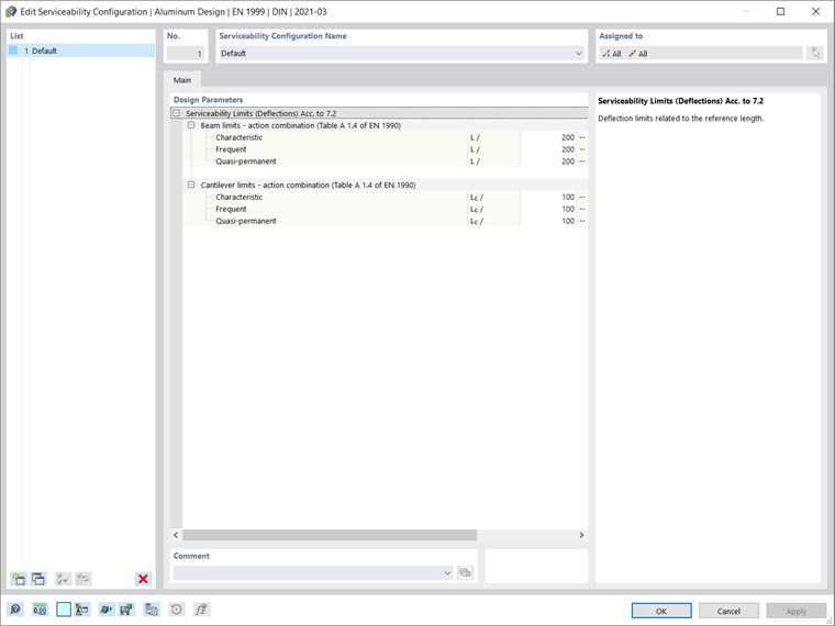
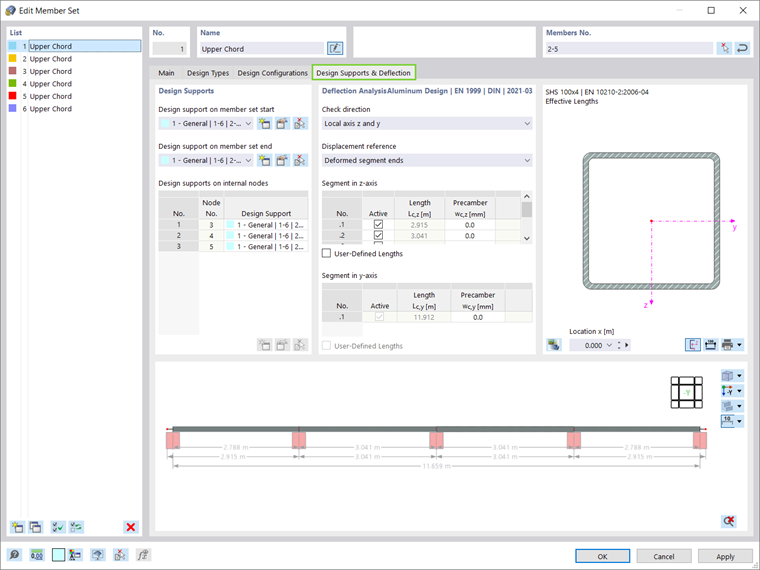
You can create serviceability configurations in terms of deflection limits, which you have to check in the design (Image 6). These limits are related to the member reference length, which is determined on the basis of the design supports you define in the Design Supports & Deflection tab. In other words, the Design Supports & Deflection window shown in Image 7 serves to define the boundary conditions for the serviceability limit state design of aluminum design.
Global Settings
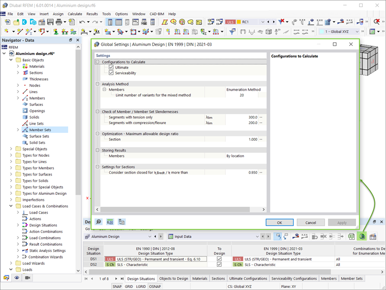
You can access the global settings for aluminum design by clicking on the Global Add-on Settings icon indicated in Image 8. These are independent of the design code, but the standard values can differ. By clicking the Resetting to Default button, the default settings of the dialog are restored according to the selected design code.
Additional Options for Aluminum Design
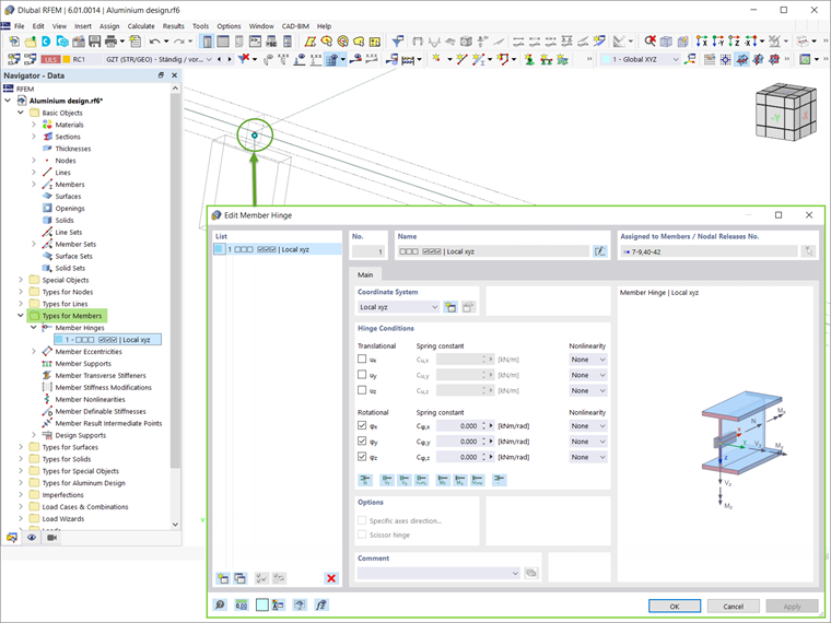
RFEM 6 offers further options that influence aluminum design. For instance, you can assign other types for members (such as member eccentricities or member hinges), as shown in Image 9. You can also consider member transverse stiffeners to stiffen areas of members susceptible to buckling. These are used, for example, for high beams or application points of large concentrated loads.
Calculation
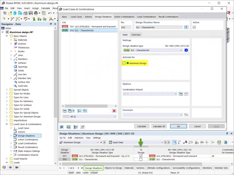
Before you start the design, it is important that you check the Input Data of the Aluminum Design add-on. For instance, the default settings imply consideration of all design situations in the design. However, you can deactivate a design situation for aluminum design by unchecking the “To be designed" check box; thus, no checks will be carried out for this design situation.
This selection is synchronized with the selection of the Aluminum Design add-on in the design situation settings, as shown in Image 10. It is important to highlight that you cannot design individual load cases, load combinations, or result combinations. Instead, you must assign these combinations to a design situation.
In a similar manner, all object types present in the model are listed in the Aluminum Design table (Image 11). By checking the “Design All” check box, all available objects will be selected for design. Alternatively, you can manually specify the objects to be designed/removed from the design by unchecking the “Design all” check box and entering the object numbers, or graphically selecting the objects of interest.
Members with a different material (for example, concrete or wood) or an unsuitable cross-section (for example, a thick-walled solid cross-section) for aluminum design are automatically recognized and excluded from design. Furthermore, aluminum surfaces will not be considered for design by the Aluminum Design add-on; you can evaluate them by employing the Stress-Strain Analysis add-on instead.
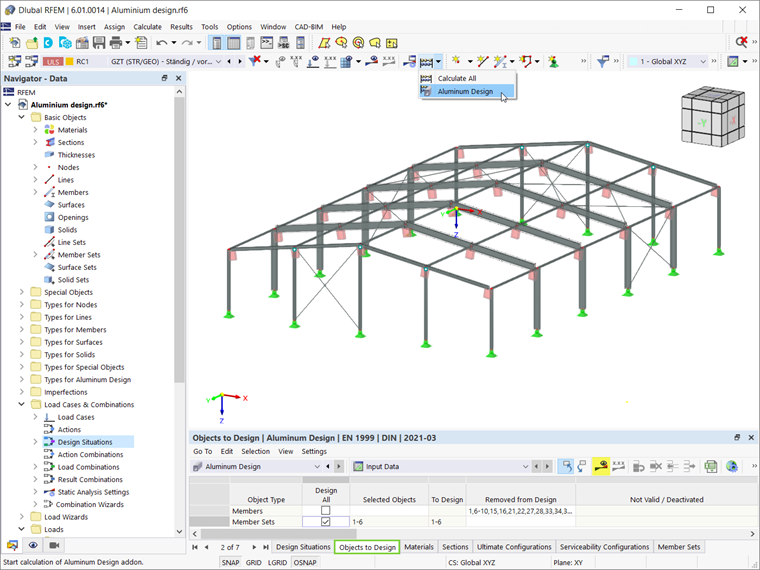
You can run the Aluminum Design add-on by selecting the Show Results button in the input table (Image 11) or by selecting Aluminum Design in the “To Calculate” dialog. After you start the calculation, the calculation progress is displayed, as well as the calculation steps and the current course of the calculation.
Results
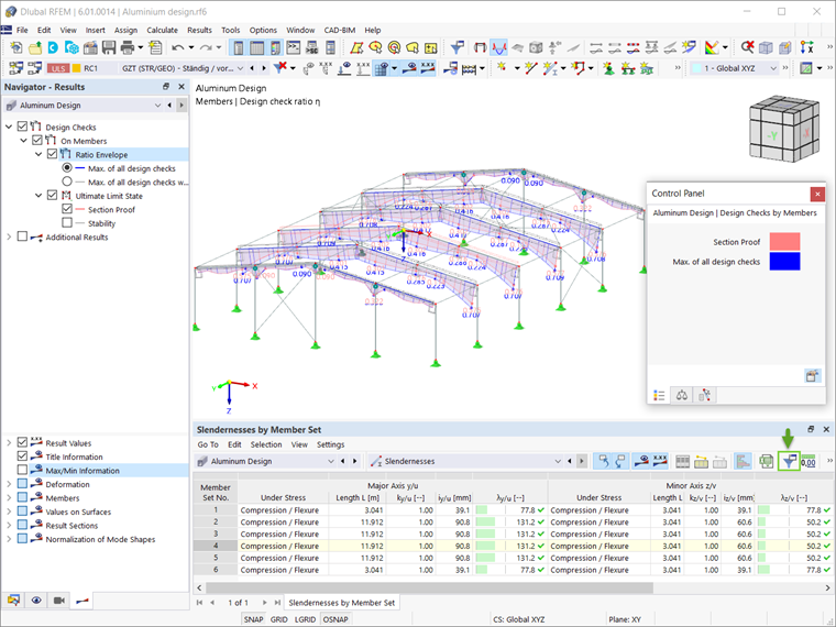
Once the calculation is finished, the governing results and the design ratios on members or member sets are available in the Results table. You can also display the results of the Aluminum Design add-on graphically via the Results tab of the navigator. If warnings or errors arise during the verifications, or a verification criterion is not met, this is shown in the Overview of the table.
In addition to these results, slenderness checks can be displayed for members or sets of members. These are based on the comparison of the slenderness for flexural buckling calculated from the ratio of the buckling length to the radius of gyration on one hand, and the limit values from the Global Settings on the other.
Since the buckling resistance is designed by the stability design, the slenderness check does not truly represent a design and it is not included in the default result table. Therefore, to show these checks, you have to activate the result tables of slenderness in the Result Table Manager, accessible through the icon indicated in Image 12.
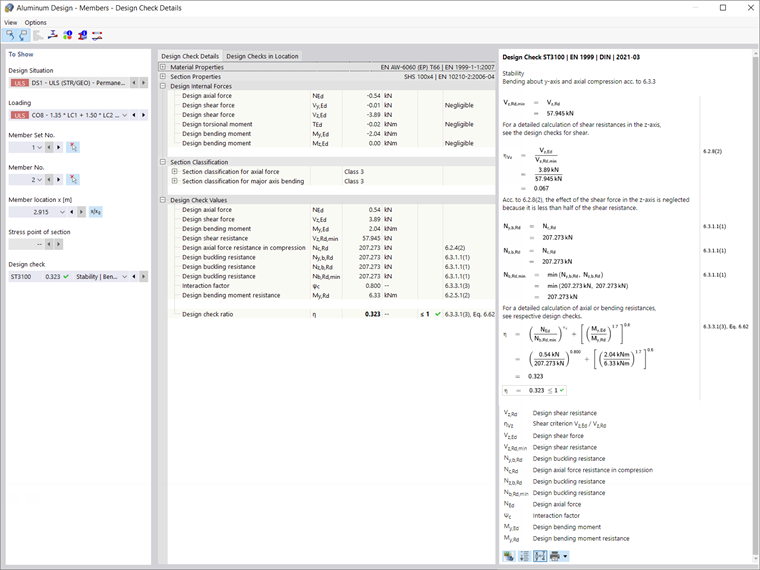
You can display detailed design checks for each design check type by double-clicking on them or using the Design Check Details icon. In addition to the formulas, the detailed results contain standard references, so that you can trace the design checks precisely and understand the performed verifications in detail.
Closing Remarks
The Aluminum Design add-on in RFEM 6 allows you to design aluminum members for the ultimate and serviceability limit states according to the European Union EN 1999-1-1:2013-12 (Eurocode 9) and United States ADM 2020 standards. The data defined in terms of materials, loading, and load and result combinations should comply with the design concept of the preferred standard.
You can apply the relevant loads in line with the common RFEM load application procedure, while you can define the data necessary for the design by activating the Design Properties of the member, or set of members, of interest. Once you define the design properties, the design can be performed and the results become available in both tabular and graphical form.


.png?mw=600&hash=49b6a289915d28aa461360f7308b092631b1446e)

