By using rigid links you can model connections between lines, members, and surfaces without defining coupling members or rigid surfaces between objects. Deformations of coupled nodes, lines, and members are identical for a rigid link.
Rigid Link of Objects
Various link types are available for selection in the list.
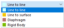
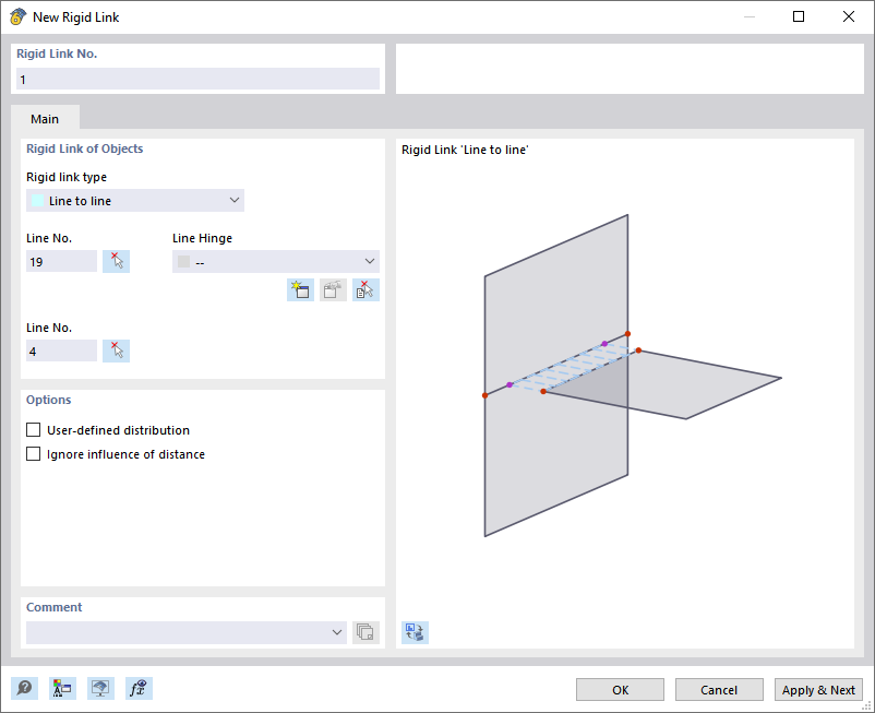
Line to Line
Enter the numbers of the two rigidly connected lines or define them graphically using the
![]() button.
button.
The link is usually created as an orthogonal connection between the lines. If you want to link them in a different way, select the User-defined distribution check box in the "Options" section. Then, you can define the link properties individually for each line (see the image Linking Lines by User-Defined Distribution).
If you want to model the connection as semi-rigid or provide it with a nonlinear property, select an already defined line hinge from the list. You can use the
![]() button to create a new hinge type.
button to create a new hinge type.
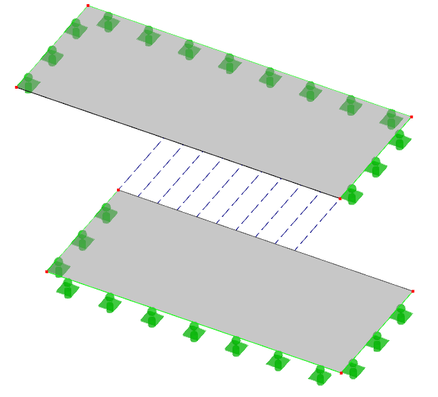
Line to Surface
Enter the numbers of the line and the surface to be rigidly linked. You can also select the objects graphically using the
![]() button.
button.
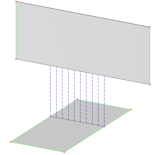
In the surface, the link line is created from the perpendicular projection onto the surface.
If you want to model the connection as semi-rigid or with a nonlinear effect, select the line hinge in the list or define a new hinge type.
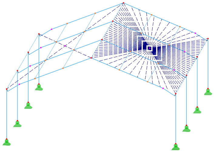
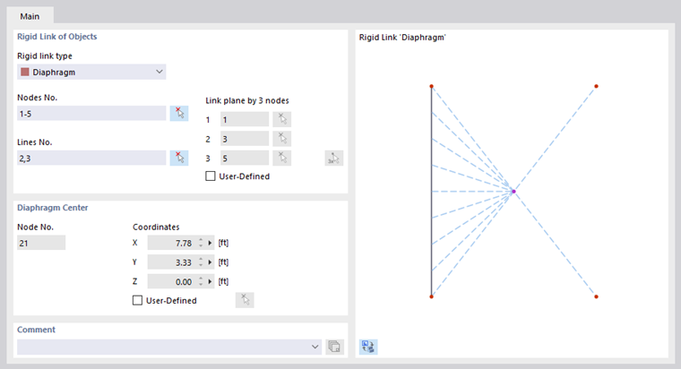
Diaphragm
With this link type, the displacements in the link plane as well as the rotations perpendicular to the plane are linked. This allows you to model, for example, stiffening diaphragms.
Enter the numbers of the linked nodes and/or lines. You can also select the objects graphically using the
![]() button.
button.
All nodes and lines must lie in one plane. This plane results automatically from the nodes and lines specified as "Link plane by 3 nodes". However, if you want to define the nodes of the plane manually, select the "User-defined" check box. This way, the input boxes become accessible.
RFEM creates a new node in the "Diaphragm Center". You can also define the coordinates of this point manually after selecting the "User-defined" check box.
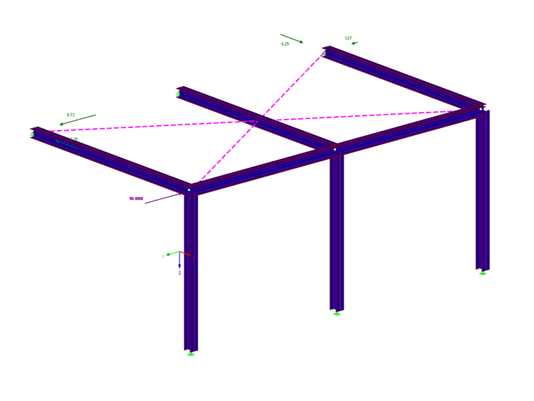
The diaphragm effect of a roof plane can be modeled by linking the edge nodes or edge lines.
Rigid Body
The concept of rigid link corresponds to that of a diaphragm. Here, the link is established as a connection between surfaces that do not lie in the same plane.
Enter the numbers of the linked nodes and/or lines of the objects. You can also select the nodes and lines graphically using the
![]() button.
button.
Options
User-Defined Distribution
If the "Line – Line" link type is selected, it is possible to link the lines by user-defined settings. You can enter the specifications in the "Distribution" tab.
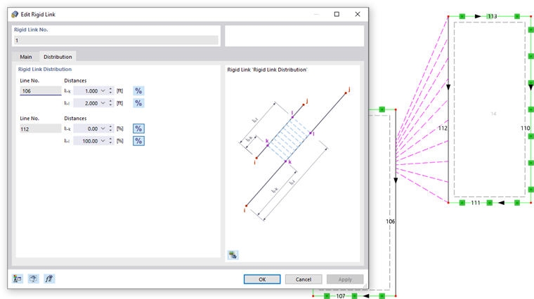
Define the "Rigid Link Distribution" by the relative distances that are related to the line start. Click the
![]() button to change the input fields to absolute lengths.
button to change the input fields to absolute lengths.
Ignoring Effect of Distance
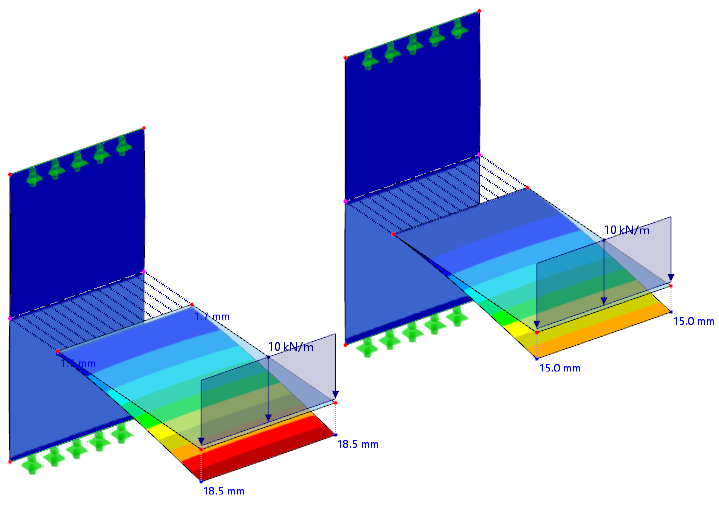
If you select the “Ignore effect of distance” check box, the distance between the linked surfaces is not taken into account in the calculation. In this case, the surfaces are assumed to be directly adjacent to each other, so that no additional moments and deformations from the link distance are effective. The option is disabled by default so that the lever arm between the linked objects is taken into account.
The following example shows how the check box affects the calculation.