The results tables of the Stresses on Surfaces category include the determined stresses with the respective design ratios.

The surface results are sorted in the tabs according to the following criteria:
- Loads (design situations, load combinations)
- Surface properties (materials, thicknesses)
- Objects (surfaces, FE mesh points)
Surface No.
For each stress type, the number of the surface with the highest value is displayed.
Mesh Node No.
The column shows the number of the FE mesh node for which the program has determined the maximum design ratio.
Mesh Node Coordinates
The global coordinates X, Y, and Z of the FE mesh nodes are shown in three columns.
Design Situation
This column indicates the number of the design situation for which the individual stresses are available.
Loading
The numbers of the load or result combinations that are governing for the respective stress are specified.
Layer No. / Side
If you have defined a surface using layer elements with the Multilayer Surfaces add-on, the numbers of the layers are indicated with the respective stresses.
For the maximum value of each type of stress, the position in the cross-section of the surface or layer at which the stress is present is specified: top, middle, or bottom.
Stress Type
This column lists the stress types that you have defined and assigned in the Surface Configurations.
Stress Existing / Limit
For each stress type, the provided stress is indicated with the corresponding limit value.
Stress Ratio η
The last column shows the stress ratios (design ratios) related to the limit value. The utilization degree is expressed by the length of the colored bar.
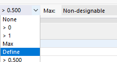
Filtering Stresses by Design Ratio
The list on the right in the table toolbar allows you to filter the tables by the utilization degree. The Max option only shows the governing maximum stress ratio for each object.

You can also define your own filter options in the format "> #.##" in this list. Thus, only the ratios greater than the user-defined value are displayed in the table.