


The Thicknesses table and the “Stress-Strain Analysis” navigator category list all thicknesses available in the model with the associated materials. The information on the thickness types is for information purposes only.

The font color indicates how the thicknesses are taken into account in the analysis.
| Black | The thickness is used both in the model and in the Objects to Analyze. |
| Blue | The thickness is not used in the model. |
| Gray | The thickness is not assigned to any of the Objects to Analyze. |
Removing Thicknesses from Analysis
For all valid thicknesses, you can exclude all surfaces with this thickness assigned from the stress-strain analysis by deactivating the “To Analyze” check box. Thus, the surfaces are sorted in the tables Objects to Analyze – Stresses and Objects to Analyze – Stress Ranges in the "Not Valid / Deactivated" column and removed from the analysis.
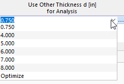
Use Other Thickness for Analysis
If you want to use a different thickness for the stress analysis than for the RFEM calculation, you can select an alternative in the "Use Other Thickness d [mm] for Analysis" column. This action has no influence on the internal forces: They are also used for the modified thickness in the stress analysis.
Once another thickness has been defined, further options are available in the cell shortcut menu (accessible by right-clicking):
- Export Thickness to RFEM
- Export All Thicknesses to RFEM
- Import Thickness from RFEM
- Import All Thicknesses from RFEM
Optimize Thickness
As an alternative to manually adjusting a thickness, the optimum thickness can be determined by the program. You can access the optimization using the list in the “Use Other Thickness d [mm] for Analysis” column (see the image Selecting Other Thickness for Analysis). You can also open the optimization dialog by double-clicking in the table row or by clicking the
![]() button in the table toolbar.
button in the table toolbar.
In the thickness editing dialog box, select the Stress analysis optimization check box in the “Main” tab. You can then define the boundary conditions in the “Stress Analysis Optimization” tab: “Minimum thickness”, “Maximum thickness” and “Thickness optimization step” (the step between the analyzed thicknesses).

During the optimization, the smallest possible thickness is determined, the design ratio of which is lower than specified in the Global Settings .
The same conditions apply for this “simplified thickness optimization” as for the use of an alternative cross-section described above: During optimization, the design checks are carried out using the internal forces of the model. The optimum variant is then entered in the table.
For a comprehensive model optimization, we recommend the Optimization Cost / CO2 Emission Estimation add-on.