38 Results
View Results:
Sort by:

The effects due to snow load are described in the American standard ASCE/SEI 7-16 and in Eurocode 1, Parts 1 through 3. These standards are implemented in the new RFEM 6 program and the Snow Load Wizard, which serves to facilitate the application of snow loads. In addition to this, the most recent generation of the program allows the construction site to be specified on a digital map, thus allowing the snow load zone to be imported automatically. These data are, in turn, used by the Load Wizard to simulate the effects due to the snow load.

In accordance with Sect. 6.6.3.1.1 and Clause 10.14.1.2 of ACI 318-19 and CSA A23.3-19, respectively, RFEM effectively takes into consideration concrete member and surface stiffness reduction for various element types. Available selection types include cracked and uncracked walls, flat plates and slabs, beams, and columns. The multiplier factors available within the program are taken directly from Table 6.6.3.1.1(a) and Table 10.14.1.2.

In RFEM 5 as well as RSTAB 8 in RF-/FOUNDATION Pro, you can save the foundation dimensions for all five foundation types as foundation templates in a user-defined database and use them later in other models.

In RF-/FOUNDATION Pro, the foundation design requires the definition of the corresponding loading (load cases, load combinations, or result combinations) for different design situations (STR, GEO, UPL, or EQU).

In RF‑/FOUNDATION Pro, reinforcement drawings are displayed after designing the foundation, where you can record all necessary structures of the reinforcement steel.

In the RF-/TIMBER Pro, RF-/TIMBER AWC, and RF-/TIMBER CSA add-on modules, you can consider the resulting deformation of a member or set of members. In addition to the local directions y and z, you have the option "R." This allows you to compare the total deflection of a girder to the limit values given in the standards.

Besides the standardized gamma method, you can display the semi-rigid composite beams also as a framework model.

In RF‑/FOUNDATION Pro, the available reinforcing steel diameters can be adjusted by the user. The adjustment of the available rebar diameters works similarly to the same function in the RF‑/CONCRETE (Members) and RF‑/CONCRETE Columns add‑on modules.

In RF-/FOUNDATION Pro, the user can freely select the proportion of the relieving soil pressure by means of the factor kred.

In RF‑/FOUNDATION Pro, you now have the option to design a foundation at one or several nodes of the model.

For a timber connection as shown in Figure 01, you can take into account the torsional spring rigidity (spring stiffness for rotation) of the connections. You can determine it by means of the slip modulus of the fastener and the polar moment of inertia of the connection.

In RFEM and RSTAB, different graphical representations of the foundation dimensions are available.

The Eurocode for DIN EN 1991‑1‑4:2010‑12 describes wind loads acting on structural systems.

RF-CONCRETE Members for RFEM or CONCRETE for RSTAB propose an automatically created reinforcement to the user if the "Design the provided reinforcement" option is selected in Window 1.6 "Reinforcement".

In RF-/FOUNDATION Pro, you can also consider the concrete cover for the foundation according to EN 1992-1-1.

In RFEM 5 and RSTAB 8, you can design foundations according to EN 1992‑1‑1 and EN 1997‑1 in the RF‑/FOUNDATION Pro add‑on module.

In addition to the basic combination rules of EN 1990, there are other combination conditions for actions on road bridges specified in EN 1991‑2 that must be taken into account. RFEM and RSTAB provide automatic combinatorics that can be activated in the General Data when selecting the standard EN 1990 + EN 1991‑2. The partial safety factors and combination coefficients depending on the action category are preset when selecting the respective National Annex.

Using the RF-TIMBER CSA module, timber column design is possible according to the CSA O86-19 standard. Accurately calculating timber member compressive resistance and adjustment factors is important for safety considerations and design. The following article will verify the factored compressive resistance in the RFEM add-on module RF-TIMBER CSA, using step-by-step analytical equations as per the CSA O86-19 standard including the column modification factors, factored compressive resistance, and final design ratio.
This article describes the design of timber panel walls due to generated horizontal loads.

In the existing standard, there were no regulations for the distribution of snow loads for elevated solar thermal and photovoltaic systems on roofs. Only distribution of the loads was advised. It was only with the National Annex DIN EN 1991-1-3/NA: 2019-04 that specific regulations were made for this.

With RF-/STEEL EC3, you can utilize nominal temperature-time curves in RFEM and RSTAB. The standard time-temperature curve (ETK), the external fire curve and the hydrocarbon fire curve are implemented. Moreover, the program provides the option to directly specify the final temperature of steel.
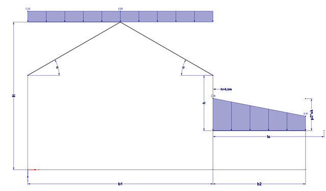
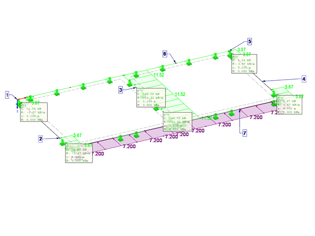
Buildings often have extensions. If the roof levels are not at the same height, this height difference (if more than 0.5 m) must additionally be considered for the snow load assumption.
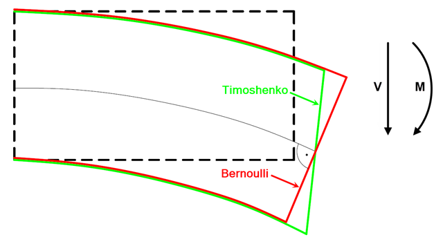
In current literature, the formulas used to determine internal forces and deformations manually are usually specified without considering the shear deformation. The deformations resulting from shear force are often underestimated in timber construction in particular.

The calculation of timber panels is carried out on simplified member or surface structures. This article describes how to determine the required stiffness.

Using the RF-TIMBER CSA module, timber beam design is possible according to the CSA O86-14 standard. Accurately calculating timber member bending resistance and adjustment factors is important for safety considerations and design. The following article will verify the factored bending moment resistance in the RFEM add-on module RF-TIMBER CSA using step-by-step analytical equations as per the CSA O86-14 standard including the bending modification factors, factored bending moment resistance, and final design ratio.

Wind blowing parallel to the surfaces of a structure can generate friction forces on these surfaces. This effect is important mainly for very large structures.

In accordance with Sec. 6.6.3.1.1 and Sec. 10.14.1.2 of ACI 318-14 and CSA A23.3-14, respectively, RFEM effectively takes into consideration concrete member and surface stiffness reduction for various element types. Available selection types include cracked and uncracked walls, flat plates and slabs, beams, and columns. The multiplier factors available within the program are taken directly from Table 6.6.3.1.1(a) and Table 10.14.1.2.
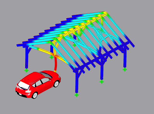
The fundamental requirements of a structural system are (according to the basis of structural design) sufficient ultimate limit state, serviceability, and resistance. Structures must be designed in such a way that no damage occurs due to events such as the impact of a vehicle.

The stiffening of timber structures is usually carried out by means of timber panels. For this purpose, structural components consisting of slabs (chipboard, OSB) are connected with members. Several articles will describe the basics of this construction method and the calculation in the RFEM program. This first article describes the basic determination of the stiffnesses as well as the calculation.

For crane runways with large spans, the horizontal load from skewing is often relevant for the design. This article describes the origin of these forces and the correct input in CRANEWAY. The practical implementation and the theoretical background are discussed.