147 Results
View Results:
Sort by:

In this article, you will learn how to model and design cable structures in RFEM 6 or RSTAB 9.

This article describes and explains the influence of bending stiffness of cables on their internal forces. Furthermore, the text provides information on how this influence can be reduced.

Lateral-Torsional Buckling (LTB) is a phenomenon that occurs when a beam or structural member is subjected to bending and the compression flange is not sufficiently supported laterally. This leads to a combination of lateral displacement and twisting. It is a critical consideration in the design of structural elements, especially in slender beams and girders.

- 001819
- Design
- Aluminum Design for RFEM 6
-
- Aluminum Design for RSTAB 9
- Concrete Design for RFEM 6
- Concrete Design for RSTAB 9
- Steel Design for RFEM 6
- Steel Design for RSTAB 9
- Timber Design for RFEM 6
- Timber Design for RSTAB 9
- Concrete Structures
- Steel Structures
- Timber Structures
- Structural Analysis & Design
- Eurocode 0
- Eurocode 2
- Eurocode 3
- Eurocode 5
- Eurocode 9
- ADM
- ANSI/AISC 360
For the serviceability of a structure, the deformations must not exceed certain limit values. This article describes an example that shows how to analyze the deflection of members using Dlubal's design add-ons.

To be able to evaluate the influence of local stability phenomena of slender structural components, RFEM 6 and RSTAB 9 provide you with the option of performing a linear critical load analysis on the cross-section level. The following article explains the basics of the calculation and the result interpretation.

With the Steel Design add-on, you can design structural steel components in the event of fire using the simple design methods according to Eurocode 3. The component temperature at the time of the design check can be determined automatically according to the temperature-time curves specified in the standard. In addition to considering a cladding for fire protection, it is also possible for you to take account of the beneficial properties of hot-dip galvanization.

Custom sections are often required in cold-formed steel design. In RFEM 6, the custom section can be created using one of the “Thin-Walled” sections available in the library. For other sections that do not meet any of the 14 available cold-formed shapes, the sections can be created and imported from the standalone program, RSECTION. For general information on AISI steel design in RFEM 6, refer to the Knowledge Base article provided at the end of the page.

The design of cold-formed steel members according to the AISI S100-16 is now available in RFEM 6. Design can be accessed by selecting “AISC 360” as the standard in the Steel Design add-on. “AISI S100” is then automatically selected for the cold-formed design (Image 01).

This article discusses the options available for determining the nominal flexural strength, Mnlb for the limit state of local buckling when designing according to the 2020 Aluminum Design Manual.

A standard scenario in timber member construction is the ability to connect smaller members by means of bearing on a larger girder member. Additionally, member end conditions may include a similar situation where the beam is bearing on a support type. In either scenario, the beam must be designed to consider the bearing capacity perpendicular to the grain according to NDS 2018 Sec. 3.10.2 and CSA O86:19 Clauses 6.5.6 and 7.5.9. In general structural design software, it is typically not possible to carry out this full design check, as the bearing area is unknown. However, in the new generation RFEM 6 and Timber Design add-on, the added 'design supports' feature now allows users to comply with the NDS and CSA bearing perpendicular to the grain design checks.

The advantage of the RFEM 6 Steel Joints add-on is that you can analyze steel connections using an FE model for which the modeling runs fully automatically in the background. The input of the steel joint components that control the modeling can be done by defining the components manually, or by using the available templates in the library. The latter method is included in a previous Knowledge Base article titled “Defining Steel Joint Components Using the Library". The definition of parameters for the design of steel joints is the topic of the Knowledge Base article “Designing Steel Joints in RFEM 6".

Steel connections in RFEM 6 are defined as an assembly of components. In the new Steel Joints add-on, universally applicable basic components (plates, welds, auxiliary planes) are available for entering complex connection situations. The methods with which connections can be defined are considered in two previous Knowledge Base articles: “A Novel Approach to Designing Steel Joints in RFEM 6" and “Defining Steel Joint Components Using the Library".

The design of cross-sections according to Eurocode 3 is based on the classification of the cross-section to be designed in terms of classes determined by the standard. The classification of cross-sections is important, since it determines the limits of resistance and rotation capacity due to local buckling of cross-section parts.

Steel has poor thermal properties in terms of fire resistance. The thermal expansion for increasing temperature is very high compared to that of other building materials, and might result in effects that were not present in the design at normal temperature due to restraint in the component. As temperature increases, steel ductility increases, whereas its strength decreases. Since steel loses 50% of its strength at temperature of 600 °C, it is important to protect components against fire effects. In the case of protected steel components, the fire resistance duration can be increased due to the improved heating behavior.

The stability checks for the equivalent member design according to EN 1993-1-1, AISC 360, CSA S16, and other international standards require consideration of the design length (that is, the effective length of the members). In RFEM 6, it is possible to determine the effective length manually by assigning nodal supports and effective length factors or, on the other hand, by importing it from the stability analysis. Both options will be demonstrated in this article by determining the effective length of the framed column in Image 1.

This technical article presents some basics for using the Torsional Warping add-on (7 DOF). It is fully integrated into the main program and allows you to consider the cross-section warping when calculating member elements. In combination with the Stability Analysis and Steel Design add-ons, it is possible to perform the lateral-torsional buckling design with internal forces according to the second-order analysis, taking imperfections into account.

In RF-/STEEL EC3, sets of members are calculated according to the General Method (EN 1993-1-1, Cl. 6.3.4) together with the stability analysis. To do this, it is necessary to determine the correct support conditions for the equivalent structure with four degrees of freedom. In most 3D models today, you can quickly lose track of the location of a set of members in the system.

In CRANEWAY, the action of a rail as "statically effective" or "statically ineffective" is defined under "Rail‑Flange Connection" in the Details dialog box. This setting controls the calculation of the load introduction length according to EN 1993-6, Tab. 5.1.

In the RF-/TIMBER Pro, RF-/TIMBER AWC, and RF-/TIMBER CSA add-on modules, you can consider the resulting deformation of a member or set of members. In addition to the local directions y and z, you have the option "R." This allows you to compare the total deflection of a girder to the limit values given in the standards.

You can make various settings in order to achieve a clearly‑arranged display of the result values. For example, some users may not want the white background in text bubbles. You can adjust the background in "Display Properties" using the Transparent and Background color option.

Besides the standardized gamma method, you can display the semi-rigid composite beams also as a framework model.

Cross-section properties in RFEM and RSTAB include different types of shear areas. This technical article explains the calculation and meaning of various values.

The automatic creation of combinations in RFEM and RSTAB with the "EN 1990 + EN 1991‑3; Cranes" option allows you to design crane runway beams as well as support loads on the rest of the structure.

Very small torsional moments in the members to be designed often prevent certain design formats. In order to neglect them and still perform the designs, you can define a limit value in RF‑/STEEL EC3 from which torsional shear stresses are taken into account.

The RF‑/STEEL EC3 add-on module can perform the design of fillet welds for all parametric, welded cross-sections of the cross-section library. For this, the option must be activated in the detail settings of the module. As an alternative, you can also use a surface model for the design.

- 000945
- Add-on Modules
- RF-FRAME-JOINT Pro 5
-
- JOINTS Steel | Column Base 8
- JOINTS Steel | DSTV 8
- JOINTS Steel | Pinned 8
- JOINTS Steel | Rigid 8
- JOINTS Steel | SIKLA 8
- JOINTS Steel | Tower 8
- JOINTS Timber | Steel to Timber 8
- JOINTS Timber | Timber to Timber 8
- RF-JOINTS Steel | SIKLA 5
- RF-JOINTS Steel | Column Base 5
- RF-JOINTS Steel | DSTV 5
- RF-JOINTS Steel | Pinned 5
- RF-JOINTS Steel | Rigid 5
- RF-JOINTS Steel | Tower 5
- RF-JOINTS Timber | Steel to Timber 5
- RF-JOINTS Timber | Timber to Timber 5
- FRAME-JOINT Pro 8
- Steel Structures
- Timber Structures
- Steel Connections
- Eurocode 3
- Eurocode 5
In addition to the result tables, you can create three-dimensional graphics in RF‑/FRAME‑JOINT Pro and RF‑/JOINTS. This is a realistic representation of a connection to scale.

For a timber connection as shown in Figure 01, you can take into account the torsional spring rigidity (spring stiffness for rotation) of the connections. You can determine it by means of the slip modulus of the fastener and the polar moment of inertia of the connection.

In the default setting, the cross-section class for each member and load case is determined automatically in the design modules. In the input window of the cross sections, however, the user can also specify the cross-section class manually; for example, if local buckling is excluded by the design.
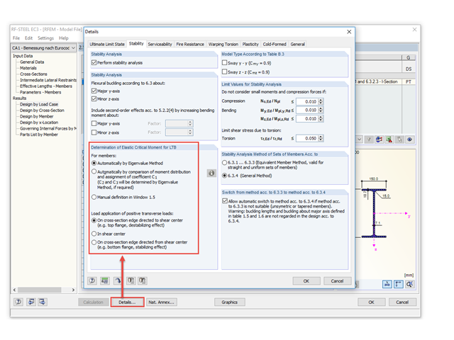
Occasionally, the question arises how to determine the correct load application point of the positive transverse loads in RF-/STEEL EC3 and RF-/STEEL AISC.

In RF‑/STEEL EC3, you can assign the same input data to several members or sets of members at the same time. The simultaneous assignment of the input data is possible for intermediate supports, effective lengths, nodal supports, member end hinges, and shear panel and rotational restraint.