73 Results
View Results:
Sort by:

The three types of moment frames (Ordinary, Intermediate, Special) are available in the Steel Design add-on of RFEM 6. The seismic design result according to AISC 341-22 is categorized into two sections: member requirements and connection requirements.

The three types of moment frames (Ordinary, Intermediate, Special) are available in the Steel Design add-on of RFEM 6. The seismic design result according to AISC 341-16 is categorized into two sections: member requirements and connection requirements.

Moment frame design according to AISC 341-16 is now possible in the Steel Design add-on of RFEM 6. The seismic design result is categorized into two sections: member requirements and connection requirements. This article covers the required strength of the connection. An example comparison of the results between RFEM and the AISC Seismic Design Manual [2] is presented.

The design of an Ordinary Concentrically Braced Frame (OCBF) and a Special Concentrically Braced Frame (SCBF) can be carried out in the Steel Design add-on of RFEM 6. The seismic design result according to AISC 341-16 and 341-22 is categorized into two sections: Member Requirements and Connection Requirements.

If you want to use a pure surface model, for example, when determining the internal forces and moments, but the structural component is still designed on the member model, you can take advantage of a result beam.

In many frame and truss structures, it is no longer sufficient to use a simple member. You often have to consider cross-section weakenings or openings in solid beams. In such cases, you can use the "Surface Model" member type. It can be integrated into the model like any other member and offers all the options of a surface model. The present technical article shows the application of such a member in an existing structural system and describes the integration of member openings.

When a concrete slab is set upon the top flange, its effect is like a lateral support (composite construction), preventing problems of torsional buckling stability. If there is a negative distribution of the bending moment, the bottom flange is subjected to compression and the top flange is under tension. If the lateral support given by the stiffness of the web is insufficient, the angle between the bottom flange and the web intersection line is variable in this case so that there is a possibility of distortional buckling for the bottom flange.

For the stability verification of members using the equivalent member method, it is necessary to define effective or lateral-torsional buckling lengths in order to determine a critical load for stability failure. In this article an RFEM 6-specific function is presented, by which you can assign an eccentricity to the nodal supports and thus influence the determination of the critical bending moment considered in the stability analysis.

A new capability within RFEM 6 when designing concrete columns is being able to generate the moment interaction diagram according to the ACI 318-19 [1]. When designing reinforced concrete members, the moment interaction diagram is an essential tool. The moment interaction diagram represents the relationship between the bending moment and axial force at any given point along a reinforced member. Valuable information is shown visually like strength and how the concrete behaves under different loading conditions.

The Steel Joist Institute (SJI) previously developed Virtual Joist tables to estimate the section properties for Open Web Steel Joists. These Virtual Joist sections are characterized as equivalent wide-flange beams which closely approximate the joist chord area, effective moment of inertia, and weight. Virtual Joists are also available in the RFEM and RSTAB cross-section database.

According to EN 1992-1-1 [1], a beam is a member of which the span is no less than 3 times the overall section depth. Otherwise, the structural element should be considered as a deep beam. The behavior of deep beams (that is, beams with a span less than 3 times the section depth) is different from the behavior of normal beams (that is, beams with a span that is 3 times greater than the section depth).
However, designing deep beams is often necessary when analyzing the structural components of reinforced concrete structures, since they are used for window and door lintels, upstand and downstand beams, the connection between split-level slabs, and frame systems.

The stability checks for the equivalent member design according to EN 1993-1-1, AISC 360, CSA S16, and other international standards require consideration of the design length (that is, the effective length of the members). In RFEM 6, it is possible to determine the effective length manually by assigning nodal supports and effective length factors or, on the other hand, by importing it from the stability analysis. Both options will be demonstrated in this article by determining the effective length of the framed column in Image 1.

The add-on modules for designing structural member components according to national, European, and international standards also show design results in addition to numerical output in tables graphically, as diagrams displayed on the framework.
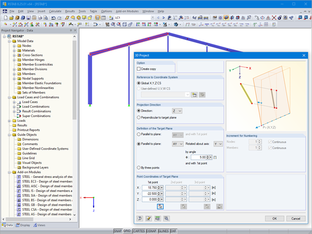
If you want to only change a few geometry parameters in a model, it is not always necessary to remove these structural parts and redefine them.

A member's boundary conditions decisively influence the elastic critical moment for lateral-torsional buckling Mcr. The program uses a planar model with four degrees of freedom for its determination. The corresponding coefficients kz and kw can be defined individually for standard-compliant cross-sections. This allows you to describe the degrees of freedom available at both member ends due to the support conditions.

Besides the standardized gamma method, you can display the semi-rigid composite beams also as a framework model.

In RFEM and RSTAB, you can visually check or display the materials used for members in the wireframe and solid models.
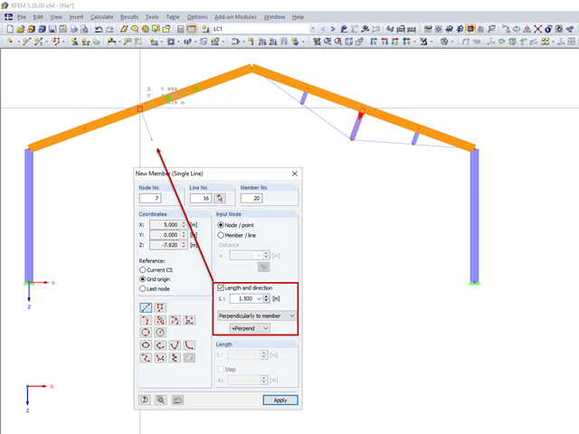
For a frame trussed from below, compression members are to be modelled perpendicular to the inclined beam. The member length and the intersection with the horizontal beam are defined.

Very small torsional moments in the members to be designed often prevent certain design formats. In order to neglect them and still perform the designs, you can define a limit value in RF‑/STEEL EC3 from which torsional shear stresses are taken into account.

General thin-walled cross-sections often have asymmetrical geometries. The principal axes of such sections are then not parallel to the horizontally and vertically aligned axes Y and Z. When determining the cross-section properties, the angle α between the center-of-gravity axis y and the principal axis u is determined in addition to the principal axis-related moments of inertia.
Not all structural elements of a real building are included in a structural model. As an example, we can look at a pipe that runs along a steel girder frame.

- 000945
- Add-on Modules
- RF-FRAME-JOINT Pro 5
-
- JOINTS Steel | Column Base 8
- JOINTS Steel | DSTV 8
- JOINTS Steel | Pinned 8
- JOINTS Steel | Rigid 8
- JOINTS Steel | SIKLA 8
- JOINTS Steel | Tower 8
- JOINTS Timber | Steel to Timber 8
- JOINTS Timber | Timber to Timber 8
- RF-JOINTS Steel | SIKLA 5
- RF-JOINTS Steel | Column Base 5
- RF-JOINTS Steel | DSTV 5
- RF-JOINTS Steel | Pinned 5
- RF-JOINTS Steel | Rigid 5
- RF-JOINTS Steel | Tower 5
- RF-JOINTS Timber | Steel to Timber 5
- RF-JOINTS Timber | Timber to Timber 5
- FRAME-JOINT Pro 8
- Steel Structures
- Timber Structures
- Steel Connections
- Eurocode 3
- Eurocode 5
In addition to the result tables, you can create three-dimensional graphics in RF‑/FRAME‑JOINT Pro and RF‑/JOINTS. This is a realistic representation of a connection to scale.

For a timber connection as shown in Figure 01, you can take into account the torsional spring rigidity (spring stiffness for rotation) of the connections. You can determine it by means of the slip modulus of the fastener and the polar moment of inertia of the connection.

The most common causes of unstable models are failing member nonlinearities such as tension members. As the simplest example, there is a frame with supports on the column footing and moment hinges on the column head. This unstable system is stabilized by a cross bracing of tension members. In the case of load combinations with horizontal loads, the system remains stable. However, if it is loaded vertically, both tension members fail and the system becomes unstable, which causes a calculation error. You can avoid such an error by selecting the exceptional handling of failing members under "Calculate" → "Calculation Parameters" → "Global Calculation Parameters".
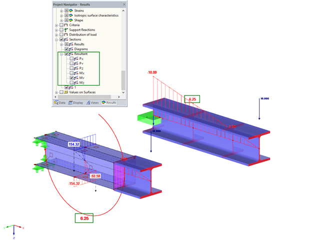
For control purposes, it is possible to display the resulting internal force in sections in RFEM. To illustrate this, the bending moment was selected in this example.
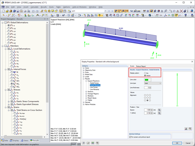
In the display properties, you can select Results → Support Reactions → Nodal Moments to specify whether a support moment should be displayed as an arc or a vector.
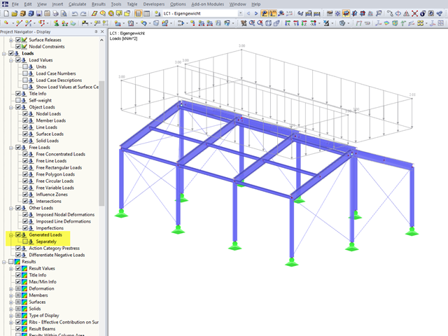
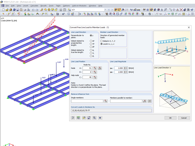
In RFEM 5 and RSTAB 8, you can generate surface loads like wind and snow by means of the implemented load generator. On frameworks, these surface loads are also displayed as surface loads in the graphic by default.
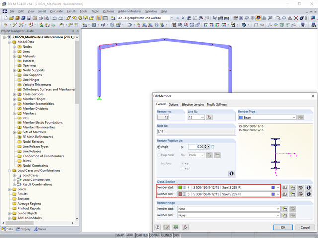
Tapers are often done using cut beam sections. When modeling, however, you have to consider certain things for checking cross‑sections and stability.

This article deals with elements concerning which the cross-section is subjected simultaneously to a bending moment, a shear force, and an axial compressive or tensile force. However, in our example we will not include loading due to shear force.

- 000487
- Modeling | Structure
- RFEM 5
-
- RF-STEEL 5
- RF-STEEL AISC 5
- RF-STEEL AS 5
- RF-STEEL BS 5
- RF-STEEL CSA 5
- RF-STEEL EC3 5
- RF-STEEL GB 5
- RF-STEEL HK 5
- RF-STEEL IS 5
- RF-STEEL NBR 5
- RF-STEEL NTC-DF 5
- RF-STEEL SANS 5
- RF-STEEL SIA 5
- RF-STEEL SP 5
- RF-ALUMINUM 5
- RF-ALUMINUM ADM 5
- RSTAB 8
- STEEL 8
- STEEL AISC 8
- STEEL AS 8
- STEEL BS 8
- STEEL CSA 8
- STEEL EC3 8
- STEEL GB 8
- STEEL HK 8
- STEEL IS 8
- STEEL NBR 8
- STEEL NTC-DF 8
- STEEL SANS 8
- STEEL SIA 8
- STEEL SP 8
- ALUMINUM 8
- ALUMINUM ADM 8
- Steel Structures
- Process Manufacturing Plants
- Stairway Structures
- Structural Analysis & Design
- Eurocode 3
- ANSI/AISC 360
- SIA 263
- IS 800
- BS 5950-1
- GB 50017
- CSA S16
- AS 4100
- SP 16.13330
- SANS 10162-1
- ABNT NBR 800
- ADM
The support conditions of a beam subjected to bending are essential for its resistance to lateral-torsional buckling. If, for example, a single-span beam is held laterally in the middle of the span, the deflection of the compressed flange can be prevented, and a two-wave eigenmode can be enforced. The critical lateral-torsional buckling moment is increased significantly by this additional measure. In the add-on modules for member design, different types of lateral supports on a member can be defined using the "Intermediate supports" input window.