82 Results
View Results:
Sort by:

The data exchange between RFEM 6 and Allplan can be done using various file formats. This article describes the data exchange of a determined surface reinforcement using the ASF interface. This allows you to display the RFEM reinforcement values as level curves or colored reinforcement images in Allplan.

This article shows how to create cross-sections using DXF files.

In many frame and truss structures, it is no longer sufficient to use a simple member. You often have to consider cross-section weakenings or openings in solid beams. In such cases, you can use the "Surface Model" member type. It can be integrated into the model like any other member and offers all the options of a surface model. The present technical article shows the application of such a member in an existing structural system and describes the integration of member openings.

The goal of using the RFEM 6 and Blender with the Bullet Constraints Builder add-on is to obtain a graphical representation of the collapse of a model based on real data of physical properties. RFEM 6 serves as the source of geometry and data for the simulation. This is another example of why it is important to maintain our programs as so-called BIM Open, in order to achieve collaboration across software domains.

The Steel Joist Institute (SJI) previously developed Virtual Joist tables to estimate the section properties for Open Web Steel Joists. These Virtual Joist sections are characterized as equivalent wide-flange beams which closely approximate the joist chord area, effective moment of inertia, and weight. Virtual Joists are also available in the RFEM and RSTAB cross-section database.

Structures in RFEM 6 can be saved as blocks and reused in other RFEM files. The advantage of dynamic blocks with respect to non-dynamic blocks is that they allow interactive modifications of the structural parameters as a result of modified input variables. One example is the possibility to add structural elements by changing only the number of bays as an input variable. This article will demonstrate the aforementioned possibility for dynamic blocks that are created by scripting.

The dialog box for editing load or result combinations is a non-modal dialog box. This means that after you open this dialog box, you can edit the combinations outside the dialog box as well. For manually defining or editing a combination, a separate dialog box can be opened parallel to the "Edit load cases and combinations" dialog box.
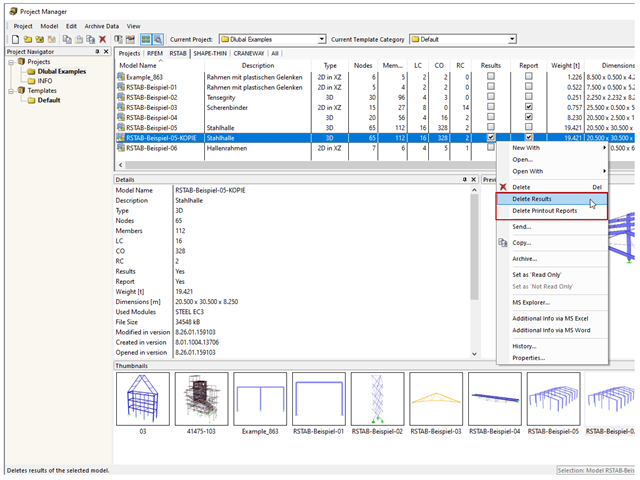
In rare cases, it may happen that an RFEM or RSTAB file cannot be opened. These files contain mostly results and report data.
Since wind on laterally open structures is not addressed in the Eurocode, the 4 cases of the German DIN 1055, Part 4 are referenced.

RFEM and RSTAB save the input data, the FE mesh, the results, the printout reports, and the 3D gITF model preview, including all visual objects, in one file.

Inserting holes in surfaces is very easy due to the large selection of tools. In order to insert holes or drilling in solids, it is necessary to keep in mind that an opening at the beginning and the end of a continuous hole must be created, as well as a surface that separates the hole from the solids.

In the age of BIM, data exchange between the various disciplines of structural engineering is becoming increasingly important. Since each software has its own specifications with regard to the description of cross-sections and materials, RFEM and RSTAB offer a conversion table (mapping file).
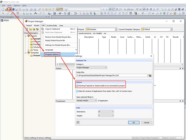
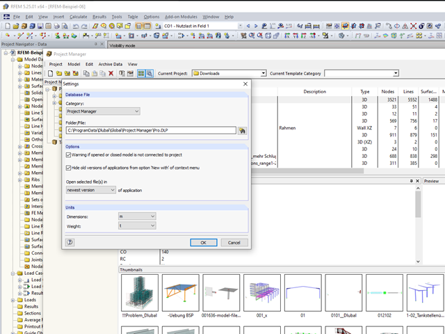
Warning Regarding Connection to Project
---
When opening a model immediately after opening the program, there is a message window asking if you want to create a new project for the model in the Project Manager.

Once you have determined the final tendon geometry in RF‑TENDON, exporting the model to a CAD program can be useful. For this purpose, the module includes the option to export the file in the .dxf file format. You can select the export function by right-clicking the workspace. After selecting the DXF format and the storage location, additional settings can be made.

In RF-/STEEL EC3, you can optimize a cross-section automatically within the design. To do this, select the corresponding cross-section in Table 1.3 or define variable parameters for a welded cross-section.
In RFEM and RSTAB, you can work with the Project Manager. It allows you to create an entire project structure and to connect it with the folders on the local hard disk.
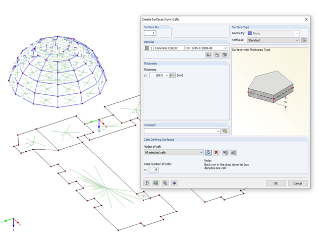
If you have imported a DXF file in RFEM or you need to add a membrane to an existing member structure, you can use the function "Tools" → "Generate Model - Surfaces" → "Surfaces from Cells", and thus quickly create planar surfaces.
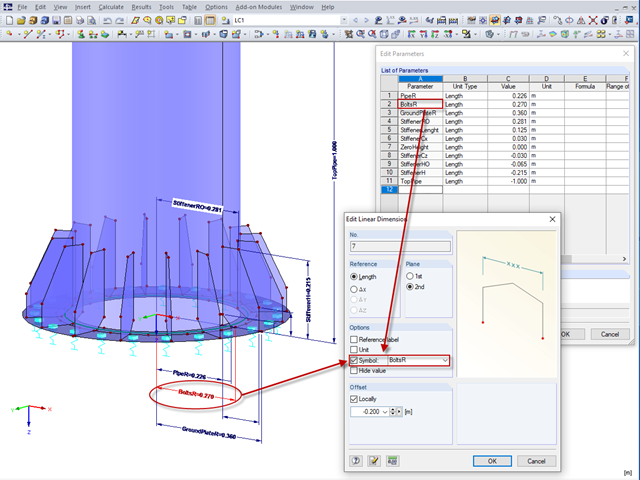
In RFEM 5 and RSTAB 8, it is useful to parameterize frequently occurring components with variable dimensions. In the Block Manager, you then can specify new dimensions and import them in a new or existing file.
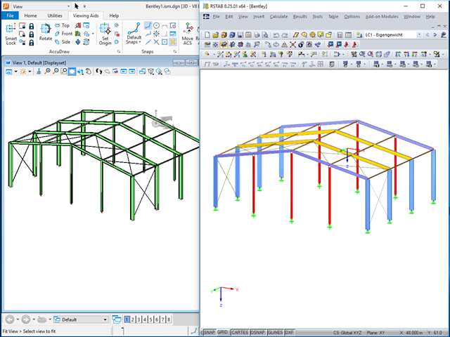
The ISM file (ISM = Integrated Structural Modeling) in RFEM and RSTAB provides an interesting option for exchanging data. If you export a model to this data format, you can view and analyze it with the free ISM viewer from Bentley.
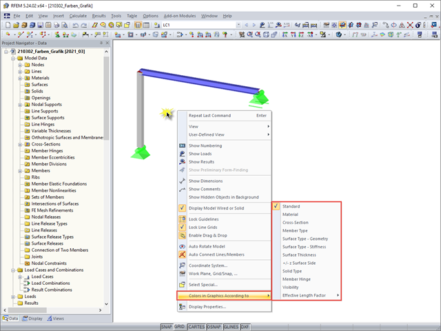
For a clearer display of the structure, you can display it in different colors. The corresponding selection can be opened by right-clicking the work window.
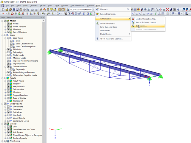
In RFEM 5 and RSTAB 8, you can view detailed information on the currently used license and installed dongle driver. In case of any problems with the license, you can send the created text file to the Dlubal Software hotline, which allows us to provide you with a fast and efficient analysis. To create the file, select "Help" → "Authorization" → "Diagnostics".
Structures react differently to wind action depending on stiffness, mass, and damping. A basic distinction is made between buildings that are prone to vibration and those that are not.

In the case of open cross-sections, the torsional load is removed mainly via secondary torsion, since the St. Venant torsional stiffness is low compared to the warping stiffness. Therefore, warping stiffeners in the cross-section are particularly interesting for the lateral-torsional buckling analysis, as they can significantly reduce the rotation. For this, end plates or welded stiffeners and sections are suitable.
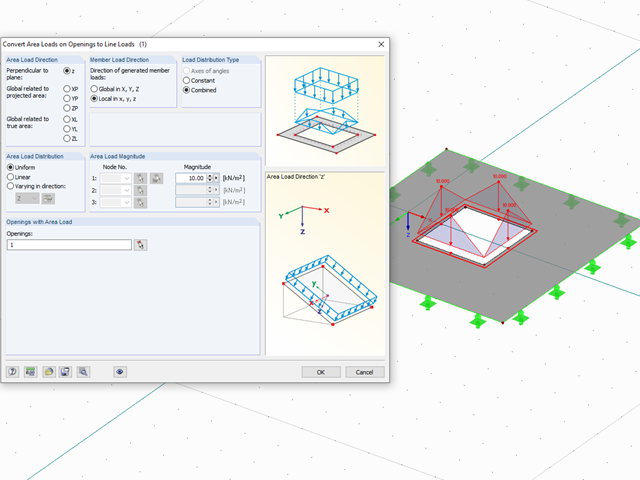
With the "Convert Area Loads on Openings to Line Loads" function, you can automatically take into account, for example, wind loads applied on windows or other loads applied on non‑bearing structures not represented in the model in openings. You can access this function via "Tools" → "Generate Loads" → "From Area Loads on Openings...."
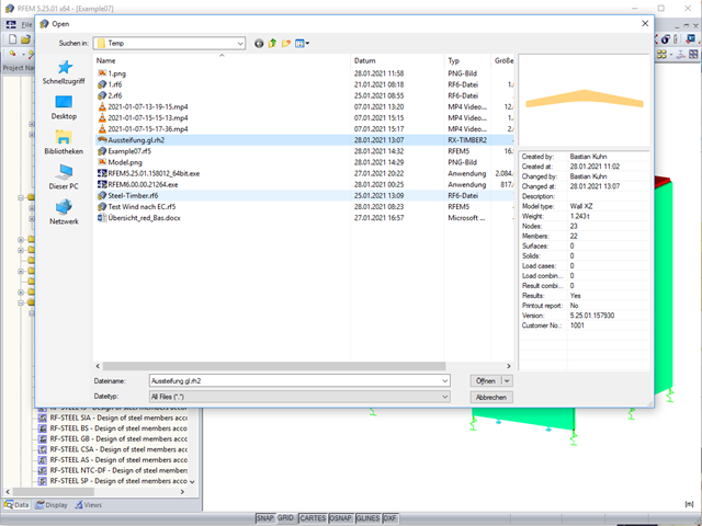
To open an RX‑TIMBER file in RFEM 5 or RSTAB 8, select the "All Files (*.*)" option as "File Type".
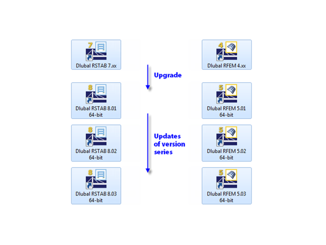
When updating within a version series (for example, RFEM 5.01.01 to 5.01.02), the old program files are removed and replaced by new ones. The project data, of course, remain unchanged. When updating to the next version series (for example, RFEM 5.02.01), the new version is installed in parallel. The program files are located in different directories, so the previous version is still available.
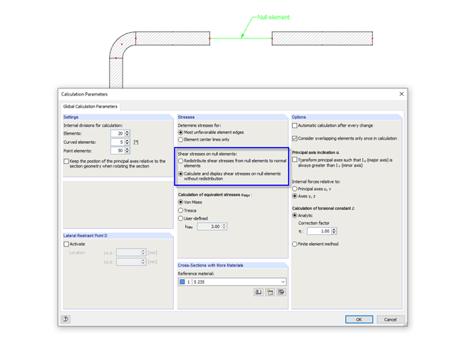
In cross‑sections created in SHAPE‑THIN, the openings, such as bolt holes, can be modeled by using the elements with zero thickness. The program provides two options for calculating shear stresses in the area of such null elements.

According to Book 631 of the DAfStb (German Committee for Structural Concrete), Chapter 2.4, the structural behavior of ceilings changes if their continuous support by walls is interrupted in areas of openings. Depending on the length of the opening area and the plate thickness, measures are necessary regarding the analysis of the ceiling in the area of the opening.
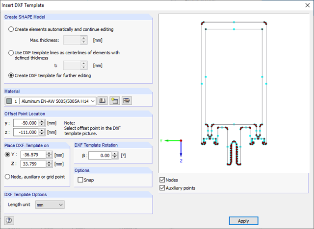
In SHAPE-THIN, you can import cross-section geometries that are available as contour or centroid layouts in DXF format and use them as a basis for modeling.
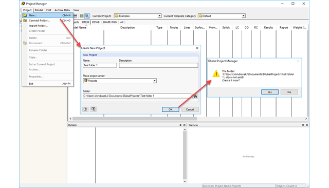
The Project Manager is installed by default when installing RFEM and RSTAB and it manages all projects and calculation files. In the Project Manager, you can link different projects to have a clear overview of the program files.