67 Results
View Results:
Sort by:

Creating a validation example for Computational Fluid Dynamics (CFD) is a critical step in ensuring the accuracy and reliability of simulation results. This process involves comparing the outcomes of CFD simulations with experimental or analytical data from real-world scenarios. The objective is to establish that the CFD model can faithfully replicate the physical phenomena it is intended to simulate. This guide outlines the essential steps in developing a validation example for CFD simulation, from selecting a suitable physical scenario to analyzing and comparing the results. By meticulously following these steps, engineers and researchers can enhance the credibility of their CFD models, paving the way for their effective application in diverse fields such as aerodynamics, aerospace, and environmental studies.

When it comes to wind loads on building type structures as per ASCE 7, numerous resources can be found to supplement design standards and aid engineers with this lateral load application. However, engineers may find it more difficult to find similar resources for wind loading on non-building type structures. This article will examine the steps to calculate and apply wind loads as per ASCE 7-22 on a circular reinforced concrete tank with a dome roof.

This example shows you how to quickly determine the buoyancy or the uplift limit state of a vessel in RFEM.

CFD calculations are in general very complex. An accurate calculation of wind flow around complicated structures is very demanding on time and computational costs. In many civil engineering applications, high accuracy is not needed and our CFD program RWIND 2 enables in such cases to simplify the model of a structure and reduce the costs significantly. In this article, some questions about the simplification are answered.

In order to be able to carry out a pushover analysis, it is necessary to transform the determined capacity curve into a simplified form. The N2 method is described in Eurocode EN 1998. This article should help to explain what a bilinearization according to the N2 method involves.

Both the determination of natural vibrations and the response spectrum analysis are always performed on a linear system. If nonlinearities exist in the system, they are linearized and thus not taken into account. They are caused by, for example, tension members, nonlinear supports, or nonlinear hinges. This article shows how you can handle them in a dynamic analysis.

Compliance with building codes, such as Eurocode, is essential to ensure the safety, structural integrity, and sustainability of buildings and structures. Computational Fluid Dynamics (CFD) plays a vital role in this process by simulating fluid behavior, optimizing designs, and helping architects and engineers meet Eurocode requirements related to wind load analysis, natural ventilation, fire safety, and energy efficiency. By integrating CFD into the design process, professionals can create safer, more efficient, and compliant buildings that meet the highest standards of construction and design in Europe.

The events of recent years remind us of the importance of earthquake engineering in seismic regions. For you as an engineer, the design of structures in earthquake-prone areas is a constant trade-off between economic efficiency – the financial possibilities – and structural safety. If a collapse is inevitable, engineers must estimate how it will affect the structure. This article aims to provide you with an option on how to perform this estimation.

Our webservice offers users the opportunity to communicate with RFEM 6 and RSTAB 9 using various programming languages. Dlubal's high-level functions (HLFs) allow you to expand and simplify the WebService's functionality. In line with RFEM 6 and RSTAB 9, using our WebService makes the engineer's work easier and faster. Check it out now! This tutorial shows you how to use the C# library by means of a simple example.

Spreadsheet programs like MS EXCEL are very popular with engineers because they allow you to simply automatize your calculations and quickly output the results. Therefore, combining MS EXCEL used as a graphical interface with Dlubal's WebService API is an obvious choice. By using the free xlwings library for Python, you can control EXCEL, and read and write values. The functionality is described in the following, using an example.

With the release of the structural analysis programs RFEM 6, RSTAB 9, RSECTION 1, and RWIND 2, Dlubal Software introduces a new generation of structural analysis programs. True to the motto "Structural analysis that is fun ...", the program provides users with universal tools with which they can meet all the requirements in structural engineering. Find out more about the latest developments at Dlubal Software in this article.

Defining the appropriate effective length is crucial in obtaining the correct member design capacity. For X-bracing that is connected at the center, engineers often wonder if the full end-to-end length of the member shall be used, or whether using half of the length to where the members are connected is sufficient. This article outlines the recommendations given by the AISC and provides an example on how to specify the effective length of the X-braces in RFEM.

Imperfections in construction engineering are associated with production-related deviation of structural components from their ideal shape. They are often used in a calculation to determine the equilibrium of forces for structural components on a deformed system.

In the age of BIM, data exchange between the various disciplines of structural engineering is becoming increasingly important. Since each software has its own specifications with regard to the description of cross-sections and materials, RFEM and RSTAB offer a conversion table (mapping file).
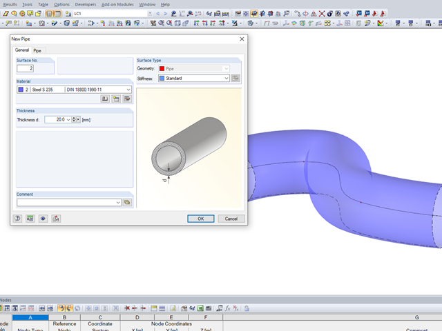
It may become necessary to analyze pipe cross‑sections as surface models in plant engineering in particular, but also when analyzing details of structural systems. For this purpose, RFEM offers the option to create pipe cross‑sections automatically by means of a line.

In order to detect the governing internal forces of a plate, a checkerboard loading is commonly used. Since it is not necessary to divide the surface into individual load segments, loading is usually carried out by means of free rectangular loads. In the case of many loads, the normal load display can become somewhat confusing.

The most common causes of unstable models are failing member nonlinearities such as tension members. As the simplest example, there is a frame with supports on the column footing and moment hinges on the column head. This unstable system is stabilized by a cross bracing of tension members. In the case of load combinations with horizontal loads, the system remains stable. However, if it is loaded vertically, both tension members fail and the system becomes unstable, which causes a calculation error. You can avoid such an error by selecting the exceptional handling of failing members under "Calculate" → "Calculation Parameters" → "Global Calculation Parameters".
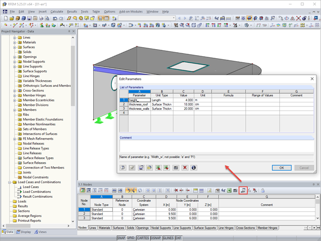
Parameterized entries provide the engineer with an efficiency-increasing tool. This allows entering structural and loading data so that they depend on certain variables. These variables (for example, length, width, live load, and so on) are called parameters.
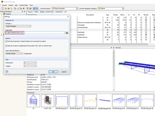
Due to rapid development in the IT sector, including structural design, the trend is towards a global model. Large projects are rarely carried out by a single engineer. Unified project management is the key to successful work in major projects.

Before creating a structural model, every user gives thought to the boundary parameters of the system and how best to represent the model. Special attention should be paid to the orientation of the global coordinate system. In engineering, the global Z‑axis is usually oriented downwards (in the direction of the dead load), while it tends to be upwards in architecture. These differences can often lead to complications during modeling; for example, when you replace global models or DXF layers.

If the geometry of a surface for which you must remove some of the existing boundary lines changes subsequently, you do not need to redefine the surface.
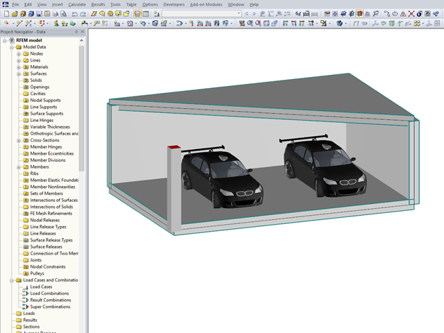
In RFEM 5 and RSTAB 8, you can add visual objects to the model in order to make a convincing impression on your client when presenting the structural model. These objects allow both laypersons and engineers to better understand the dimensions of the system.
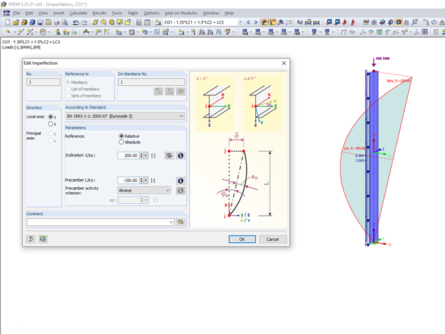
In the world of construction engineering, the word "imperfections" has a specific meaning. In general, it describes the incompleteness of a structure or the deviation of a structural component from an ideal shape caused by the production.
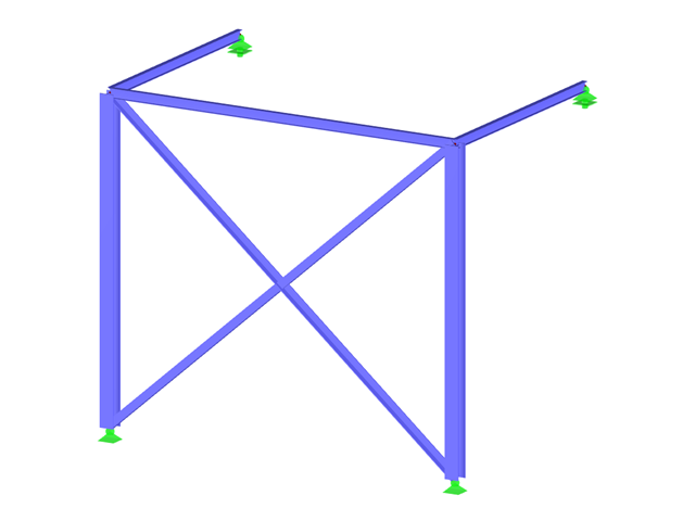
If the calculation of a member model according to the second-order analysis is terminated with an error message, this instability is often caused by failed tension members: As soon as compressive forces appear in a tension member during a calculation step, this member is no longer considered in the following iterations. Thus, the model can become unstable.
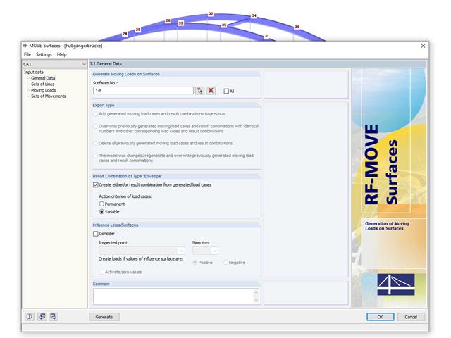
RF-MOVE Surfaces facilitates the generation of load cases from different positions of moving loads. Based on the load positions of the moving load, the program generates separate load cases for RFEM 5. Optionally, an enveloping result combination of all load positions is created.
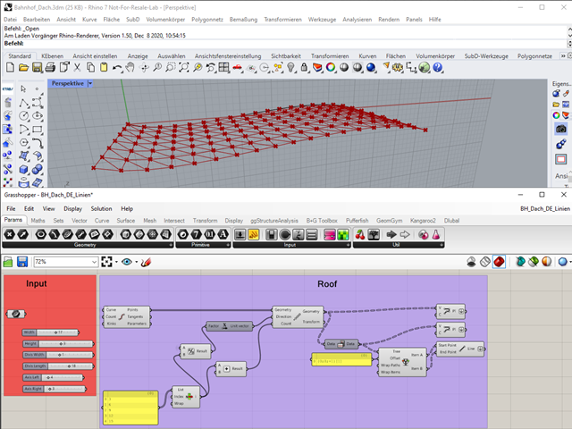
"A good tool is half the job done": This proverb could be applied equally to the software industry. The more a program is task-tailored, the more efficiently the tasks can be solved. The variety and complexity of today's problems, especially in structural engineering, require specifically tailored solutions. Creating your own programs by means of textual programming requires in-depth knowledge and a great ability to abstract. Understandably, only very few engineering offices face this challenge. For this reason, there are additional software solutions providing the user with a visual development environment.
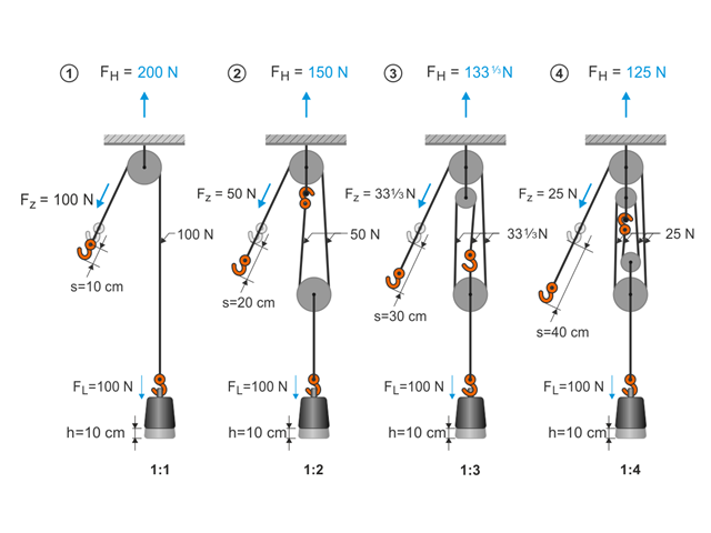
This article describes the basic principles and modeling approaches of pulley systems in RFEM.

The elastic deformations of a structural component due to a load are based on Hooke's law, which describes a linear stress-strain relation. They are reversible: After the relief, the component returns to its original shape. However, plastic deformations lead to irreversible deformations. The plastic strains are usually considerably larger than the elastic deformations. For plastic stresses of ductile materials such as steel, yielding effects occur where the increase in deformation is accompanied by hardening. They lead to permanent deformations - and in extreme cases to the destruction of the structural component.

The European standard EN 1993-1-8, Section 4.5.3.3. provides the user with a simplified method for the ultimate limit state design of fillet welds. According to the standard, the design is fulfilled if the design value of the resultant acting on the fillet weld area is smaller than the design value of the weld's load-bearing capacity. Thus, if you want to dimension the weld for a surface model, you will be faced with a variety of results due to the nature of FEM calculations. Therefore, we show in the following text how to determine the force components from the model.
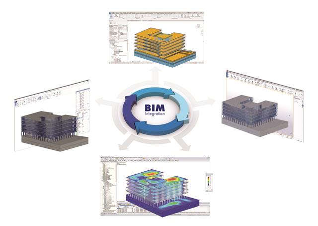
The building and construction industry is increasingly digitized. Structural engineers, a smaller group in the construction industry, are not always considered to be engineers who follow the latest trends immediately. There is often good reason for this. Many consider this to be the reason that topics such as utilizing the BIM method are not yet the standard in structural engineering. However, the past few years have shown that a process of rethinking has begun, and new digital trends are being picked up and applied.