33 Results
View Results:
Sort by:

The goal of using the RFEM 6 and Blender with the Bullet Constraints Builder add-on is to obtain a graphical representation of the collapse of a model based on real data of physical properties. RFEM 6 serves as the source of geometry and data for the simulation. This is another example of why it is important to maintain our programs as so-called BIM Open, in order to achieve collaboration across software domains.

Surfaces in building models can be of many different sizes and shapes. All surfaces can be considered in RFEM 6 because the program allows to define different materials and thicknesses as well as surfaces with different stiffness and geometry types. This article focuses on four of these surface types: rotated, trimmed, without thickness, and load transfer.
RWIND 2 is a program for generating wind loads based on CFD (Computational Fluid Dynamics). The wind flow numerical simulation is generated around any building, including irregular or unique geometry types, to determine the wind loads on surfaces and members. RWIND 2 can be integrated with RFEM/RSTAB for the structural analysis and design or as a stand-alone application.

RWIND 2 is a program for generating wind loads based on CFD (Computational Fluid Dynamics). The wind flow numerical simulation is generated around any building, including irregular or unique geometry types, to determine the wind loads on surfaces and members. RWIND 2 can be integrated with RFEM/RSTAB for the structural analysis and design or as a stand-alone application.
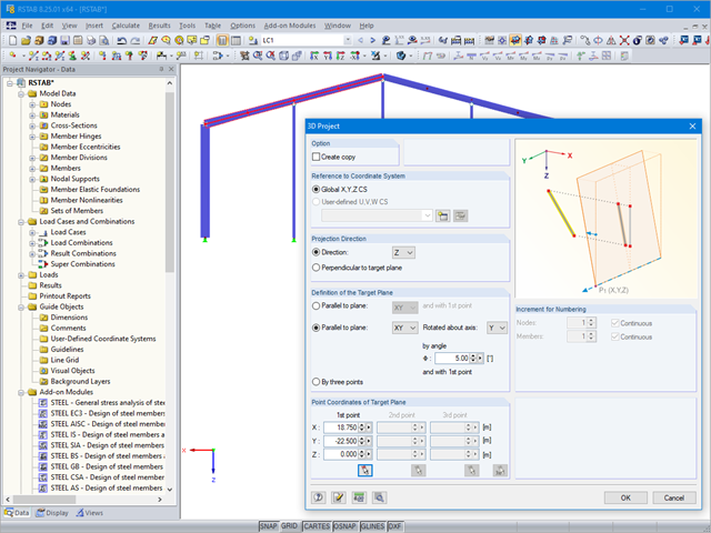
If you want to only change a few geometry parameters in a model, it is not always necessary to remove these structural parts and redefine them.

In addition to the geometry and shape of a flat roof, you can also take into account the formation of an eaves area when generating the loading.

In RF‑TENDON and RF‑TENDON Design, you can review and adjust the code‑dependent factors, calculation parameters, and calculation methods using the "Code" button. You can display the settings and adjustment options according to a chapter of a code, selecting the "Grouping" option in the dialog box.

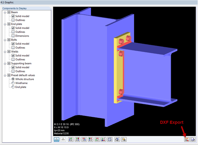
Once you have determined the final tendon geometry in RF‑TENDON, exporting the model to a CAD program can be useful. For this purpose, the module includes the option to export the file in the .dxf file format. You can select the export function by right-clicking the workspace. After selecting the DXF format and the storage location, additional settings can be made.
In the Formula Editor environment, you can specify any parameters (lengths, force values, and so on) to control load and geometry data in the modeling.
One of the advantages of entering the structure in RFEM is the complete freedom when selecting the geometry. You can easily select a structure where re‑entrant rolling corners are given as shown in the image.

You can use the elastic support option to avoid singularities due to a fixed nodal support in RFEM. This can be defined directly in the dialog box of the nodal support as a column in Z. It is necessary to take into account the geometry of the column, the material, and the support conditions. Here, we want to look at the option of modeling the column as a surface foundation.

When using the RF‑GLASS add‑on module, you can define just the geometry in the main program, as well as the load situation of the structural component to be designed. The respective support conditions and all further design-relevant definitions (for example, the layer structure and support conditions), can be further specified in RF‑GLASS.
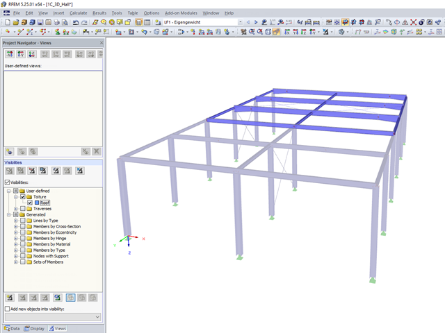
User-defined visibilities facilitate program handling. Once created, any model groups can be quickly hidden or shown. This facilitates, among other things, the analysis of the results in larger 3D structures, as well as the creation of the report. When changing the geometry, the existing visibilities may have to be updated.

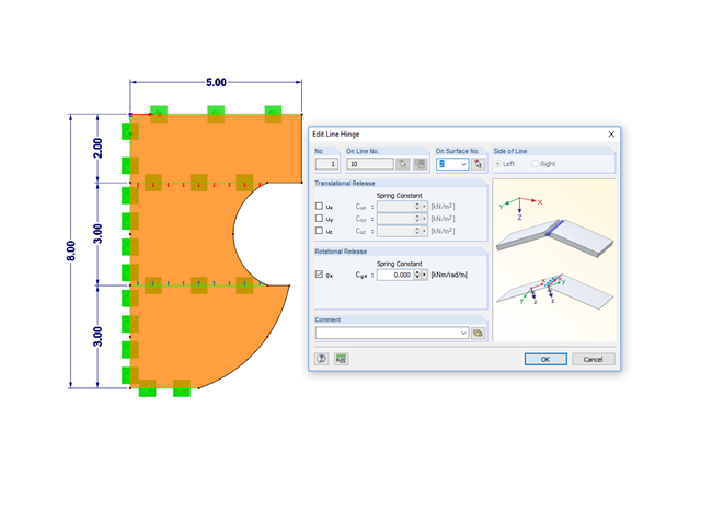
If the geometry of a surface for which you must remove some of the existing boundary lines changes subsequently, you do not need to redefine the surface.

In the RF-/FOUNDATION Pro add-on module, you can select the automatic dimensioning of the foundation plate geometry. In the dialog box for the design parameters of the foundation plate, you can, for example, specify the increment for the increase of the base area and the foundation plate thickness. You can also automatically increase the covering for a stabilizing effect of the geotechnical designs.
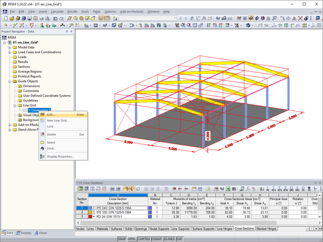
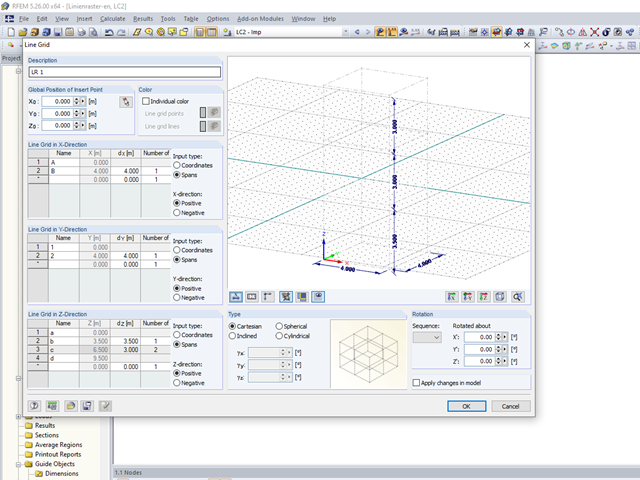
As a quick tool for changing the structure geometry, the "Line Grid" option is available in "Project Navigator – Data" under "Guide Objects".

The wind load of rectangular rounded structural components is a complex matter. The equivalent forces from wind load depend on the strength of the circulating wind load and the component geometry.
.png?mw=640&hash=6e011ea537587ceb48d9e642d642150a151c551e)
The ASCE 7-16 standard requires both balanced and unbalanced snow load case scenarios for a structure's design consideration. While this may be more intuitive for flat or even gable/hip type roofs, the determination of snow loads is increasingly difficult for arch roofs due to complex geometry. However, with guidance from ASCE 7-16 on snow load calculations for curved roofs and RFEM's efficient load application tools, it is possible to consider both balanced and unbalanced snow loads for a reliable and safe structure design.
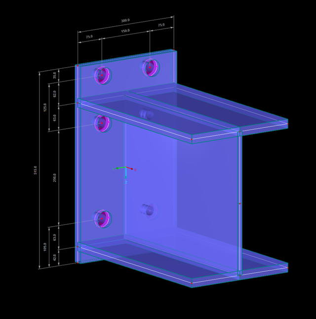
Especially if the adjacent area of connection points is to be analyzed, if the geometry and load of the connection do not correspond to the standard specifications, and/or if a model is to be analyzed using an FE model (for example, in plant engineering), the connections must also be evaluated in detail on the FE model.
![System and Loading According to [1]](/en/webimage/009455/2418877/01-en-png.png?mw=640&hash=c76563b459152b19c98197ea6ba342be89d9a5bc)
The product range of Dlubal Software contains various modules for the design of steel and timber connections. The RF-/JOINTS Steel – Column Base add-on module allows you to analyze footings of hinged or restrained steel column bases. The fastener selection, foundation geometry, and material quality are crucial for the cost-effective and safe design of the column base.
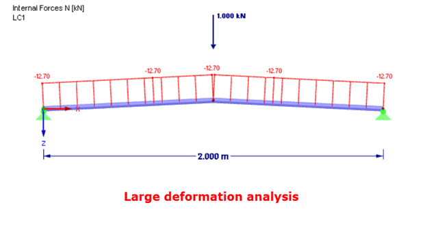
In the case of a post-critical failure, a substantial change occurs in the geometry of a structure. After reaching the instability of the equilibrium, a stable, strength position is reached again. The post-critical analysis requires an experimental approach. It is necessary to manually load the structure in increments, step by step.
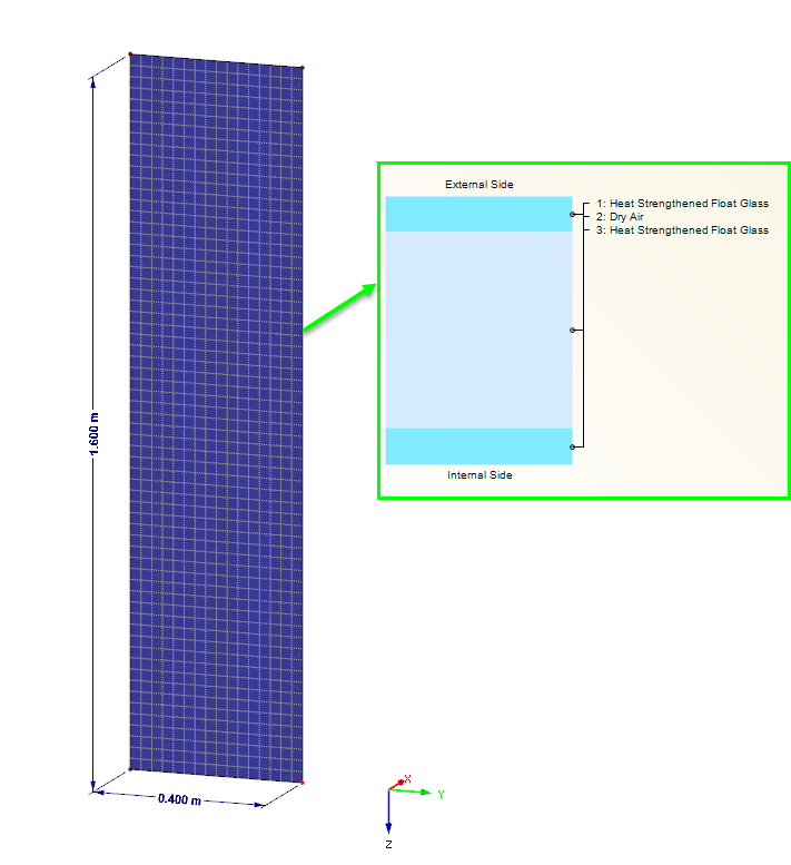
Loading panes of insulating glass due to climatic effects are clearly regulated in DIN 18008. In the case of the corresponding pane geometry, this load type can also govern for the ultimate limit state design. The FE design on the entire structure with the space between panes represented as the volume of a gas provides exact results for the analysis. However, a plausibility check is also becoming increasingly important. This article shows various options for performing these checks.
![Parameters of Effective Slab Width (Figure 5.3 [1])](/en/webimage/009561/2419376/01-en-png.png?mw=640&hash=c76563b459152b19c98197ea6ba342be89d9a5bc)
In the case of combined FEM structures (surface and member elements) as well as folded plate structures, it is possible to attribute a beam structure for the design on a member to a fictitious T-beam cross-section, whose geometry depends on the effective width. When using the "Rib" member type in RFEM, the stiffness is represented by a slab component (surface element) and a web component (member element). This approach has some design specifics that are explained in this article.
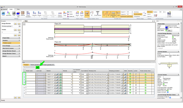
With program version RFEM 5.06, you can edit several tendons in the RF‑TENDON add‑on module simultaneously. To do this, it is necessary to select the corresponding tendons in the tendon arrangement table.
- 001262
- Add-on Modules
- RFEM 5
-
- RSTAB 8
- RF-JOINTS Steel | Column Base 5
- RF-JOINTS Steel | Pinned 5
- RF-JOINTS Timber | Steel to Timber 5
- RF-JOINTS Steel | Tower 5
- RF-JOINTS Steel | SIKLA 5
- JOINTS Steel | Column Base 8
- JOINTS Steel | Pinned 8
- JOINTS Timber | Steel to Timber 8
- JOINTS Steel | Tower 8
- JOINTS Steel | SIKLA 8
- Steel Connections
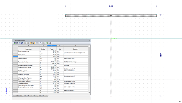
The design of cross-sections usually requires many different cross-section properties. In RFEM and RSTAB, all required properties of standardized cross-sections are available in the cross-section library and can be used directly for the calculation. If the cross-sections are not standardized, SHAPE-THIN allows you to use these cross-sections, too. You can simply enter the geometry to determine all required cross-section properties. The following example shows the calculation of a shear area on a practical example.

The form-finding process in RF-FORM-FINDING displaces the corner nodes of FE elements of a membrane surface in space until the defined surface stress is in equilibrium with the boundary conditions. This displacement is independent of the element geometry. In the case of elements with four corner nodes, the free displacement may cause spatial drilling in the element plane and thus exceed the validity limits of the calculation; therefore, triangular elements are generally recommended for form‑finding systems. Triangular elements remain independent of the corner node displacement and stay within the calculation limitations.
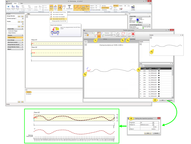
In RF-TENDON, you can import tendon geometry from a DXF file. Thus, you can use basically any tendon geometry.
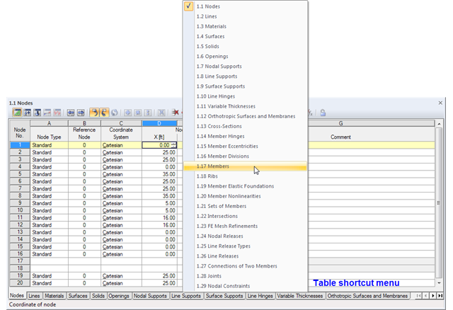
The geometry data of an RFEM model are currently managed in 29 tables, so not all of the tabs are displayed at once. To open a particular table, we recommend using the navigation menu that you can open by right-clicking on any tab. A shortcut menu appears, where you can quickly access the desired input table.
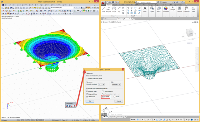
In RFEM, there are a file‑based and a direct DXF interface. The file-based DXF interface allows you to export the data in a DXF file that is transferred directly into an open AutoCAD file. In the interface dialog box, you can select which data are to be exported (results as isolines, result values, or finite element mesh with boundary and integration lines).