28 Wyniki
Wyświetl wyniki:
Sortuj według:
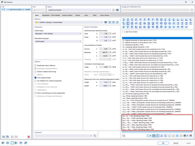
Aby umożliwić ocenę wpływu lokalnych zjawisk stateczności smukłych elementów, w programach RFEM 6 i RSTAB 9 można przeprowadzić liniową analizę obciążenia krytycznego na poziomie przekroju. Poniższy artykuł poświęcony jest podstawom obliczeń i interpretacji wyników.

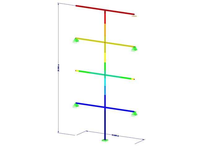
Analiza modalna jest punktem wyjścia do analizy dynamicznej układów konstrukcyjnych. Można ją wykorzystać do określenia wartości drgań własnych, takich jak częstotliwości drgań własnych, kształty drgań własnych, masy modalne i efektywne współczynniki masy modalnej. Wynik ten może zostać wykorzystany do obliczeń drgań oraz do dalszych analiz dynamicznych (na przykład obciążenia widmem odpowiedzi).
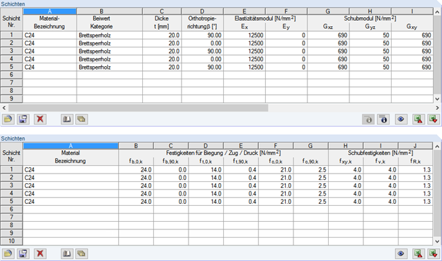
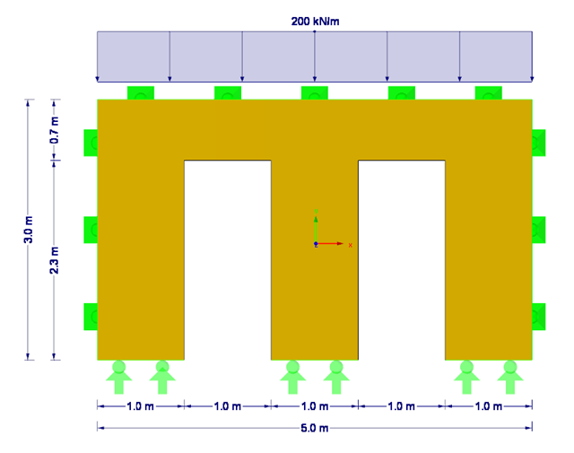
Poniższy artykuł opisuje wymiarowanie ściany z drewna klejonego krzyżowo, podatnej na wyboczenie, opisanej w pierwszej części tej serii artykułów, z wykorzystaniem metody prętów zastępczych, zgodnie z [1] sekcja 6.3.2. Analiza wyboczenia zostanie przeprowadzona jako analiza naprężeń ściskających ze zmniejszoną wytrzymałością na ściskanie. W tym celu określany jest współczynnik niestateczności kc, zależny przede wszystkim od smukłości elementu i typu podpory.
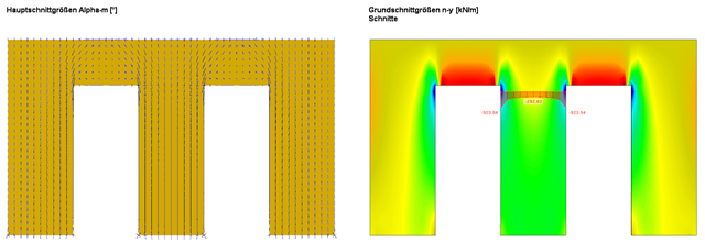
W tym artykule opisano, jako alternatywę dla metody prętów zastępczych, wyznaczyć siły wewnętrzne ściany podatnej na wyboczenie zgodnie z analizą drugiego rzędu z uwzględnieniem imperfekcji, a następnie przeprowadzić wymiarowanie przekroju na zginanie i ściskanie.

Analiza dynamiczna w RFEM 6 i RSTAB 9 jest podzielona na kilka rozszerzeń. Rozszerzenie Analiza modalna jest niezbędne dla wszystkich innych rozszerzeń do analizy dynamicznej, ponieważ przeprowadza analizę drgań własnych dla modeli prętów, powierzchni i brył.
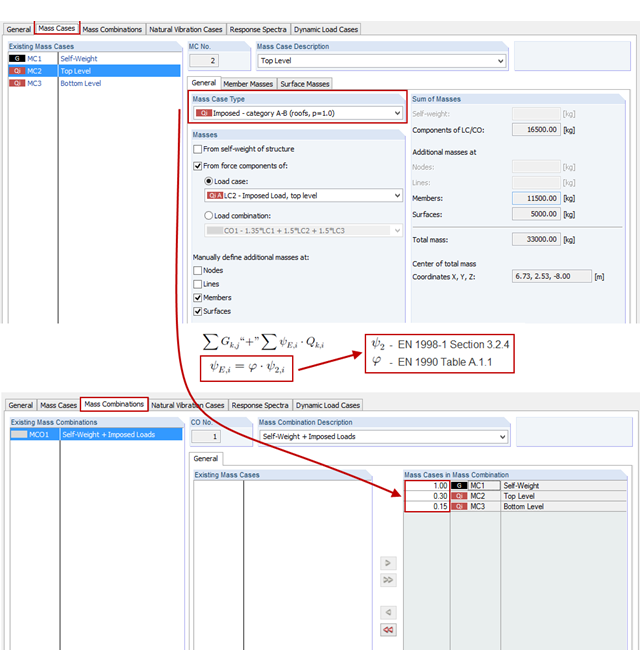
Nowy moduł RF-/DYNAM Pro - Natural Vibrations jest dostępny od wydania programów RFEM w wersji 5.04.xx i RSTAB w wersji 8.04.xx. Massen können nun direkt aus Lastfällen oder Lastkombinationen importiert werden.
![Spektrale Beschleunigung Sa [m/s²] versus Eigenfrequenz f [Hz] eines schmalbandigen Antwortspektrums nach EN 1998-1 [1]](/pl/webimage/009251/466397/01-de.png?mw=640&hash=9f6ca6566391e0348354d64018782d9ffd5f7c70)
In einem multimodalen Antwortspektrenverfahren ist es wichtig, eine ausreichende Anzahl von Eigenwerten der Struktur zu ermitteln und deren dynamische Antworten zu berücksichtigen. Vorschriften wie die EN 1998-1 [1] und andere internationale Standards schreiben vor, 90 % der Strukturmasse zu aktivieren. To oznacza: so viele Eigenwerte zu bestimmen, dass die Summe der effektiven Modalmassenfaktoren größer 0.9 ist.
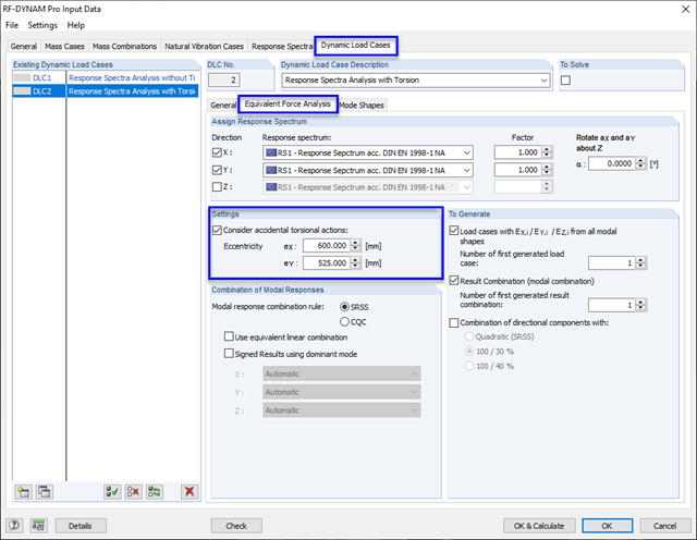
W celu uwzględnienia niedokładności dotyczących położenia mas w analizie spektrum odpowiedzi, normy do obliczeń sejsmicznych określają zasady, które muszą być stosowane zarówno w uproszczonej, jak i multimodalnej analizie spektrum odpowiedzi. Reguły te opisują następującą ogólną procedurę: masa kondygnacji musi zostać przesunięta o pewien mimośród, co powoduje powstanie momentu skręcającego.

Nowa generacja oprogramowania RFEM umożliwia przeprowadzanie obliczeń stateczności zbieżnych prętów drewnianych zgodnie z metodą prętów zastępczych. Zgodnie z tą metodą obliczenia można przeprowadzić, jeżeli spełnione są wytyczne normy DIN 1052, sekcja E8.4.2 dla zmiennych przekrojów. W różnych publikacjach technicznych metoda ta jest również stosowana w przypadku Eurokodu 5. W tym artykule pokazano, jak zastosować metodę prętów zastępczych dla belki dachowej o zbieżnej wysokości.
Mit RF-/DYNAM Pro Ersatzlasten ist es möglich, eine Ersatzlastberechnung anhand des multimodalen Antwortspektren-Verfahrens zu durchzuführen. Im dargestellten Beispiel wurde dies für einen Mehrmassenschwinger durchgeführt.
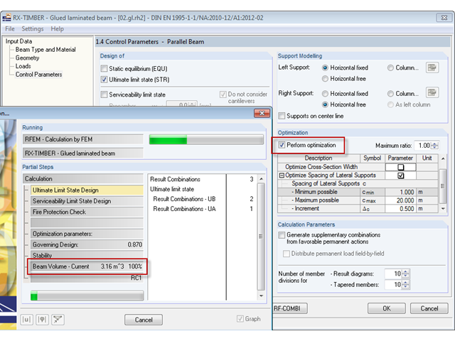
Im Programm RX-HOLZ kann optional eine Optimierung der Kippaussteifung erfolgen. Bei dieser Selektion wird iterativ die minimal notwendige Länge der Kippaussteifungen ermittelt.
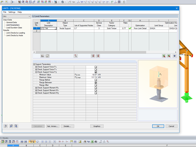
Mit dem Modul LIMITS ist es möglich die Tragfähigkeit von Stäben, Stabenden, Knoten, Knotenlagern und Flächen (nur RFEM) anhand einer definierten Grenztragfähigkeit zu vergleichen. Des Weiteren können Knotenverschiebungen sowie Querschnittsabmessungen kontrolliert werden. In diesem Beispiel sollen Stützenfüße eines Carports mit den vom Hersteller angegebenen, maximal zulässigen, Kräften verglichen werden.
W module dodatkowym RF-LAMINATE można wymiarować elementy konstrukcyjne wykonane z drewna klejonego krzyżowo. Since the design is a pure elastic stress analysis, it is necessary to additionally consider the stability issues (flexural buckling and lateral-torsional buckling).
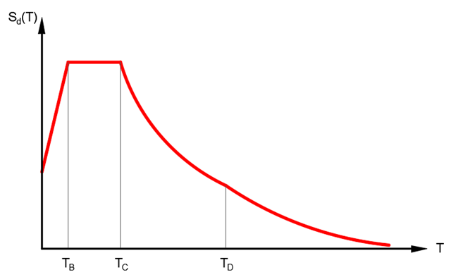
Analiza spektrum odpowiedzi jest jedną z najczęściej stosowanych metod obliczeniowych w przypadku obciążenia trzęsieniem ziemi. Metoda ta ma wiele zalet, a najważniejsza z nich to możliwość znacznego uproszczenia obliczeń. Skomplikowany charakter obciążenia jakim jest trzęsienie ziemi jest upraszczany do postaci, która umożliwia przeprowadzenie analizy o rozsądnym stopniu pracochłonności. Wadą metody jest natomiast to, że w wyniku tego uproszczenia traci się część informacji o obciążeniu. Sposobem na zniwelowanie tego ograniczenia może być zastosowanie równoważnej kombinacji liniowej podczas łączenia odpowiedzi modalnych. W poniższym artykule wyjaśniono to bardziej szczegółowo na konkretnym przykładzie.
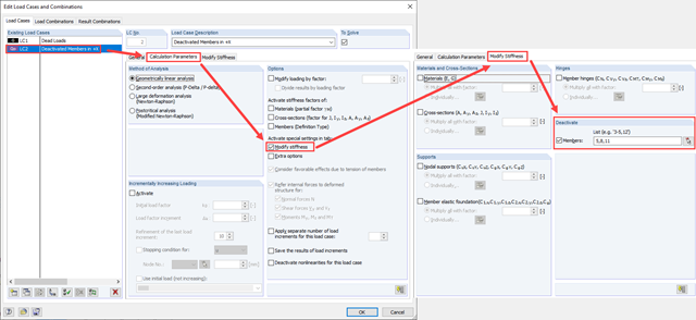
Zarówno analiza drgań własnych, jak i analiza spektrum odpowiedzi przeprowadzane są na układzie liniowym. Jeżeli w modelu występują nieliniowości, podlega on linearyzacji, dzięki czemu elementy nieliniowe nie są brane pod uwagę w dalszej analizie. W praktyce jednak bardzo często wprowadzamy do modeli elementy "tylko rozciągane". W przedstawionym artykule opisano, w jaki sposób można je poprawnie zastąpić dla przeprowadzenia liniowej analizy dynamicznej.
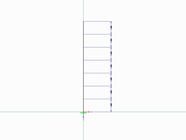
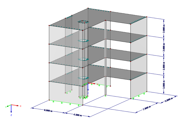
![Redukcja budynku do konstrukcji wspornikowej. Kondygnacje stanowią poszczególne punkty masy. Ugięcie spowodowane normalnymi siłami ściskającymi pokazanymi w (a) jest (b) przeliczane na równoważne momenty przemieszczenia lub siły tnące [2]]](/pl/webimage/009762/467694/01-de-png.png?mw=640&hash=52805a227240ecddbd69b1d113348bf2749c3f9e)
Zgodnie z EN 1998-1 sekcje 2.2.2 i 4.4.2.2 [1] do sprawdzania stanu granicznego nośności należy przeprowadzić obliczenia z uwzględnieniem teorii drugiego rzędu (efekt P-Δ). Dieser Einfluss darf nur vernachlässigt werden, wenn der Empfindlichkeitsbeiwert der gegenseitigen Stockwerksverschiebung θ kleiner 0,1 ist.
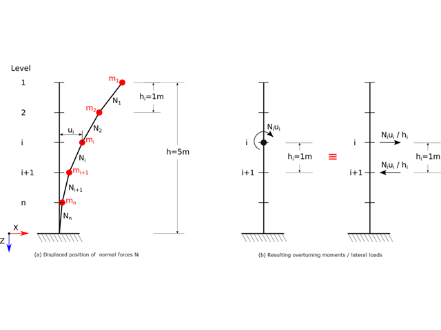
Zgodnie z normami EN 1998-1 sekcje 2.2.2 i 4.4.2.2 do obliczeń stanu granicznego nośności należy przeprowadzić obliczenia z uwzględnieniem teorii drugiego rzędu (efekt P-Δ). Efekt ten nie musi być uwzględniany tylko w przypadku, gdy współczynnik wrażliwości międzykondygnacyjnej jest mniejszy niż 0,1.
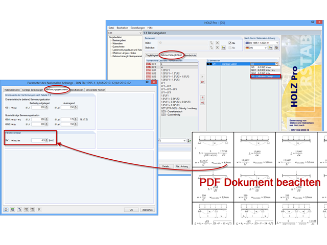
Mit dem Zusatzmodul RF-/HOLZ Pro ist es möglich, für die Bemessung nach EN 1995-1-1 den aus der DIN 1052 bekannten Schwingungsnachweis zu führen. Dieser besagt, dass unter ständiger und quasi-ständiger Einwirkung die Durchbiegung am ideellen Einfeldträger einen Grenzwert (nach DIN 1052 6 mm) nicht überschreiten darf. Wenn man den Zusammenhang zwischen Eigenfrequenz und Durchbiegung für einen mit konstanter Streckenlast belasteten, gelenkigen Einfeldträger berücksichtigt, so resultiert aus den 6 mm eine Mindesteigenfrequenz von zirka 7,2 Hz.
Artykuł Wyboczenie giętno-skrętne w konstrukcji drewnianej | Teoria wyjaśnia teoretyczne podstawy analitycznego określania momentu krytycznego M crit lub krytycznego naprężenia zginającego σcrit dla wyboczenia giętno-skrętnego belki zginanej. W poniższym artykule przedstawiono przykłady obliczeniowe, których celem jest weryfikacja wyników analizy wartości własnych względem wyników analitycznych.

Zarówno analiza drgań własnych, jak i analiza spektrum odpowiedzi przeprowadzane są na układzie liniowym. Jeżeli w modelu występują nieliniowości, podlega on linearyzacji, dzięki czemu elementy nieliniowe nie są brane pod uwagę w dalszej analizie. Mogą to być na przykład pręty rozciągane, podpory nieliniowe lub przeguby nieliniowe. W tym artykule pokazano, w jaki sposób można nimi zarządzać w analizie dynamicznej.

Rozszerzenie Projektowanie konstrukcji aluminiowych dla RFEM 6 wymiaruje pręty aluminiowe ze względu na stan graniczny nośności i użytkowalności zgodnie z Eurokodem 9. Ponadto możliwe jest wymiarowanie zgodnie z ADM 2020 (norma amerykańska).

Wymiarowanie prętów stalowych formowanych na zimno zgodnie z AISI S100-16 jest teraz dostępne w programie RFEM 6. Design can be accessed by selecting “AISC 360” as the standard in the Steel Design add-on. “AISI S100” is then automatically selected for the cold-formed design (Image 01).
![Belka rozwidlona z rozproszonym obciążeniem (Źródło: [3])](/pl/webimage/009690/467522/01-de-png.png?mw=640&hash=52805a227240ecddbd69b1d113348bf2749c3f9e)
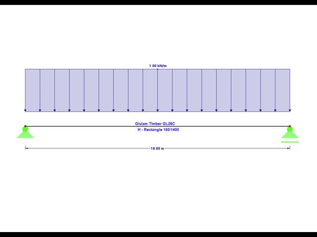
Belki z drewna klejonego o dużej rozpiętości są zazwyczaj podparte na słupie żelbetowym z ograniczeniami skrętnymi.
Poniższy artykuł opisuje sposób przeprowadzania obliczeń belki dwuprzęsłowej, poddanej zginaniu, z zastosowaniem modułu dodatkowego RF-/STEEL EC3 zgodnie z EN 1993-1-1. Globalne zakłócenie stateczności zostanie wykluczone, dzięki zastosowaniu dostatecznych środków zapewniających stateczność.
Podczas wprowadzania i przenoszenia obciążeń poziomych, takich jak wiatr lub obciążenia sejsmiczne, w modelach 3D pojawiają się coraz większe trudności. Aby uniknąć takich problemów, niektóre normy (np. ASCE 7, NBC) wymagają uproszczenia modelu za pomocą przepon, które rozkładają obciążenia poziome na elementy konstrukcyjne przenoszące obciążenia, ale nie mogą samodzielnie przenosić zginania (tzw. „Przepona”).
W RF-DYNAM Pro - Equivalent Loads, równoważne obciążenia sejsmiczne mogą być obliczane według różnych norm. Poprzez obliczenie obciążeń równoważnych dla każdej postaci własnej nie jest możliwe bezpośrednie uzyskanie ścinania poprzecznego dla każdej kondygnacji, aby przeprowadzić późniejszą analizę. Poniższy przykład opisuje możliwość szybkiego i efektywnego obliczenia ścinania poprzecznego.

Aby ocenić, czy w obliczeniach dynamicznych konieczne jest również uwzględnienie analizy drugiego rzędu, w normie EN 1998‑1, sekcje 2.2.2 i 4.4.2.2 zawarto współczynnik wrażliwości międzykondygnacyjnego znoszenia θ. Można ją obliczyć i przeanalizować za pomocą programów RFEM 6 i RSTAB 9.
.png?mw=640&hash=bfebd5ea2d4f77a817fa987424a23a799b3fe711)
W przypadku smukłych belek zginających o dużym stosunku h/w, obciążonych w kierunku słabej osi bezwładności, występują problemy ze statecznością. Wynika to z ugięcia pasu ściskanego.