43 Wyniki
Wyświetl wyniki:
Sortuj według:

Niniejszy artykuł dotyczy długotrwałego ugięcia konstrukcji betonowych zgodnie z ACI 318 i CSA A23.3.

Dzięki rozszerzeniu Projektowanie konstrukcji stalowych możliwe jest projektowanie konstrukcji stalowych zgodnie z normą AISC 360-22. W poniższym artykule porównano wyniki obliczeń zwichrzenia zgodnie z rozdziałem F z analizą wartości własnych.

Ocena przemieszczenia kondygnacji w budynku jest kluczowa dla zapewnienia zadowalających parametrów konstrukcyjnych poprzez ograniczenie przemieszczenia kondygnacji. Nadmierne znoszenie może powodować niestateczność systemu i powodować uszkodzenia elementów niekonstrukcyjnych, takich jak ściany działowe. W tym artykule opisano procedurę wyznaczania przemieszczeń międzykondygnacyjnych zgodnie z ASCE 7-22 i rozszerzeniem Model budynku w programie RFEM 6.

Norma ASCE 7-22 [1], rozdz. 12.9.1.6 określa, kiedy efekty P-delta powinny być uwzględniane podczas przeprowadzania analizy modalnego spektrum odpowiedzi dla obliczeń sejsmicznych. W NBC 2020 [2], Wys. 4.1.8.3.8.c jedynie w niewielkim stopniu wymaga uwzględnienia przechyłów spowodowanych interakcją obciążeń grawitacyjnych z konstrukcją odkształconą. Z tego względu podczas przeprowadzania analizy sejsmicznej mogą wystąpić sytuacje, w których efekty drugiego rzędu, znane również jako P-delta, muszą zostać uwzględnione.

W rozszerzeniu Projektowanie konstrukcji stalowych dla programu RFEM 6 dostępne są trzy typy ram sprężystych (zwykłe, pośrednie i specjalne). Wyniki obliczeń sejsmicznych zgodnie z AISC 341-22 są podzielone na dwie sekcje: wymagania dotyczące prętów i połączeń.
Rozszerzenie Wymiarowanie drewna umożliwia wymiarowanie słupów drewnianych zgodnie ze standardową metodą ASD 2018 NDS. Dokładne wyznaczenie nośności na ściskanie oraz współczynników redukcyjnych dla prętów drewnianych jest konieczne dla bezpieczeństwa konstrukcji. Poniższy artykuł weryfikuje maksymalną wytrzymałość na wyboczenie krytyczną obliczoną w module rozszerzeniowym Wymiarowanie drewna przy użyciu równań analitycznych krok po kroku zgodnie z normą NDS 2018, w tym współczynników dostosowania przy ściskaniu, skorygowanej wartości obliczeniowej na ściskanie i końcowego stopnia wyboczenia.

Rozszerzenie Projektowanie konstrukcji stalowych w RFEM 6 oferuje teraz możliwość przeprowadzania obliczeń sejsmicznych zgodnie z AISC 341-16 i AISC 341-22. Obecnie dostępnych jest pięć typów systemów sejsmicznych (SFRS).

W rozszerzeniu Projektowanie konstrukcji stalowych dla programu RFEM 6 dostępne są trzy typy ram sprężystych (zwykłe, pośrednie i specjalne). Wyniki obliczeń sejsmicznych zgodnie z AISC 341-16 są podzielone na dwie sekcje: wymagania dotyczące prętów i połączeń.

Obliczanie ramy momentowej zgodnie z AISC 341-16 jest teraz możliwe w rozszerzeniu Projektowanie konstrukcji stalowych dla programu RFEM 6. Wynik obliczeń sejsmicznych jest podzielony na dwie sekcje: wymagania dotyczące prętów i połączeń. W tym artykule omówiono wymaganą wytrzymałość połączenia. Przedstawiono przykładowe porównanie wyników pomiędzy RFEM a AISC Seismic Design Manual.

Obliczenia zwykłej ramy stężonej koncentrycznie (OCBF) oraz SCBF (specjalnej konstrukcji szkieletowej stężonej koncentrycznie) można przeprowadzić w rozszerzeniu Projektowanie konstrukcji stalowych dla programu RFEM 6. Wyniki obliczeń sejsmicznych zgodnie z AISC 341-16 i 341-22 są podzielone na dwie sekcje: Wymagania dotyczące prętów i połączeń.
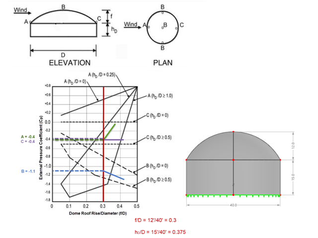
Jeśli chodzi o obciążenia wiatrem konstrukcje budowlane zgodnie z ASCE 7, można znaleźć wiele źródeł, które mogą uzupełnić normy projektowe i pomóc inżynierom w zastosowaniu obciążeń poprzecznych. Jednak inżynierom może być trudniej znaleźć podobne zasoby dla obciążeń wiatrem na konstrukcjach innych niż budynki. W tym artykule omówiono etapy obliczania i przykładania obciążeń wiatrem zgodnie z ASCE 7-22 na okrągłym zbiorniku żelbetowym z dachem w kształcie kopuły.

Zarówno analiza drgań własnych, jak i analiza spektrum odpowiedzi przeprowadzane są na układzie liniowym. Jeżeli w modelu występują nieliniowości, podlega on linearyzacji, dzięki czemu elementy nieliniowe nie są brane pod uwagę w dalszej analizie. Mogą to być na przykład pręty rozciągane, podpory nieliniowe lub przeguby nieliniowe. W tym artykule pokazano, w jaki sposób można nimi zarządzać w analizie dynamicznej.
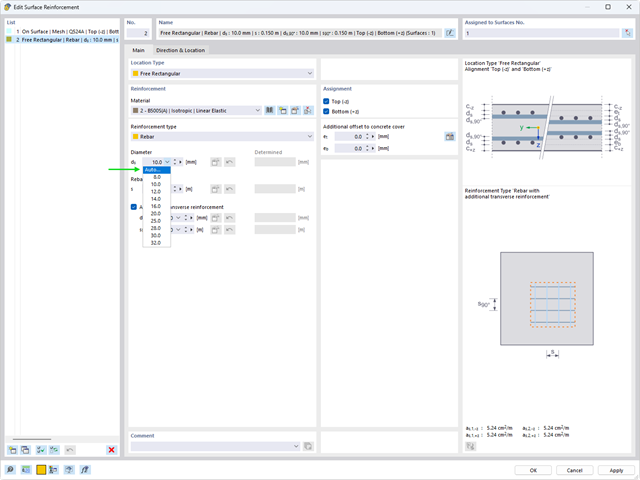
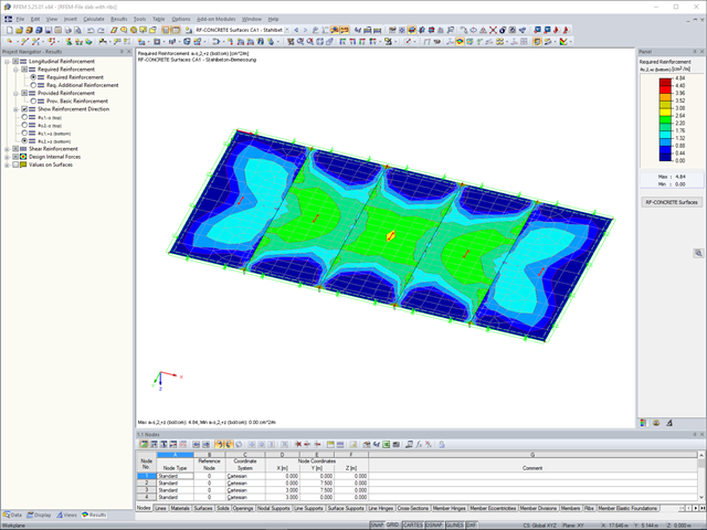
Automatyczny proces wymiarowania zbrojenia określa zbrojenie powierzchniowe, które zapewnia wymaganą ilość zbrojenia wynikającego z obliczeń.

Osłony przeciwwiatrowe to specjalne konstrukcje tekstylne, które mają za zadanie chronić środowisko przed szkodliwymi cząsteczkami chemicznymi, jak również ograniczać erozję wietrzną, przyczyniając się do ochrony cennych zasobów. RFEM i RWIND są używane do analizy konstrukcji wiatrowej dla jednostronnej interakcji płyn-konstrukcja (FSI).
W tym artykule pokazano, jak wymiarować osłony przeciwwiatrowe przy użyciu programów RFEM i RWIND.
W tym artykule pokazano, jak wymiarować osłony przeciwwiatrowe przy użyciu programów RFEM i RWIND.
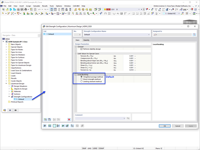
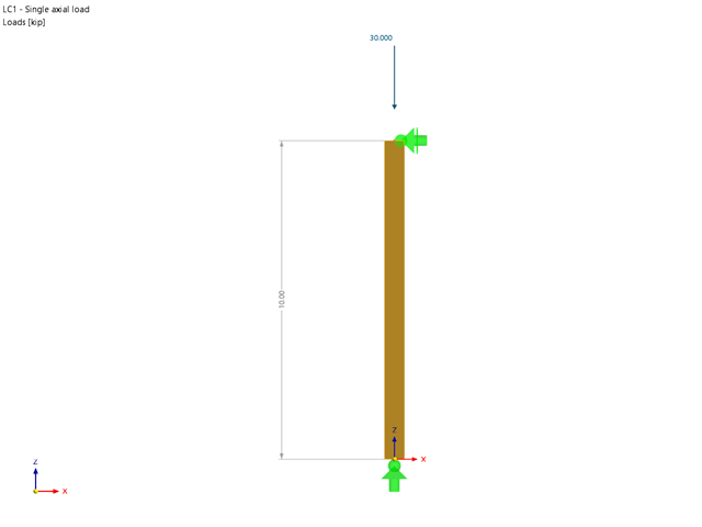
W tym artykule omówiono dostępne opcje określania nominalnej wytrzymałości na zginanie Mnlb dla stanu granicznego wyboczenia lokalnego, podczas projektowania zgodnie z Aluminium Design Manual (Podręcznik projektowania konstrukcji aluminiowych 2020).
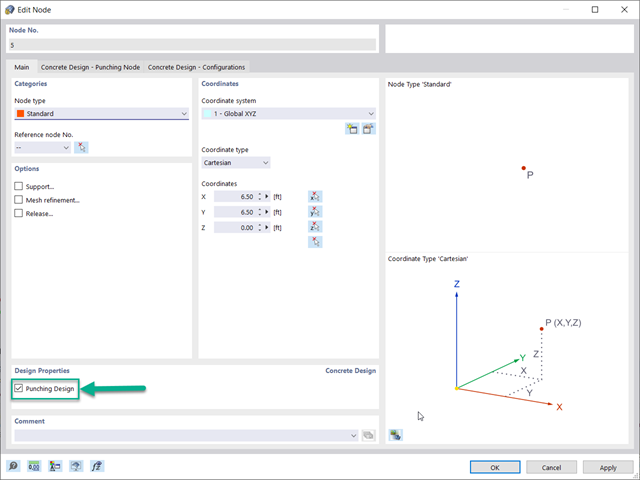
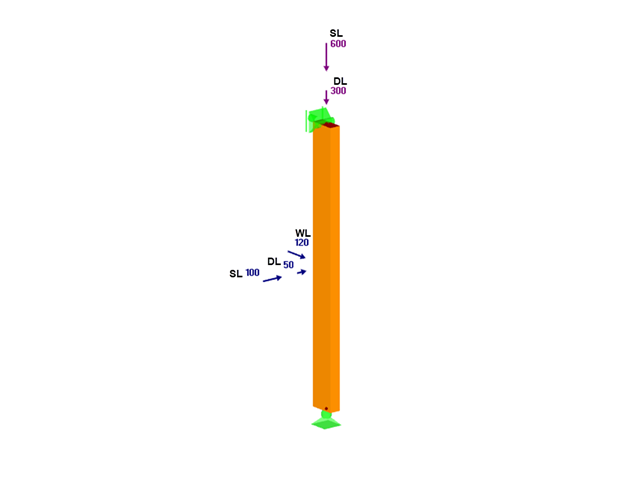
Optymalnym scenariuszem, w którym należy zastosować obliczenia wytrzymałości na przebicie, zgodnie z ACI 318-19 lub CSA A23.3:19, jest sytuacja, w której w płycie występuje duża koncentracja obciążeń lub sił reakcji występujących w jednym węźle. W programie RFEM 6 węzeł, w którym występuje przebicie, nazywany jest węzłem z przebiciem. Przyczyny tak dużej koncentracji sił mogą być spowodowane przez słup, siłę skupioną lub podporę węzłową. Łączenie ścian może również powodować obciążenia skupione na końcach, narożach i na końcach obciążeń liniowych i podpór.
Konstrukcje murowe można modelować i analizować w programie RFEM 6 za pomocą rozszerzenia Projektowanie konstrukcji murowych, który wykorzystuje do obliczeń metodę elementów skończonych. Zakładając, że w programie zaimplementowano nieliniowy model materiałowy, można modelować złożone konstrukcje murowe oraz przeprowadzać analizę statyczną i dynamiczną, aby przedstawić nośność konstrukcji murowej oraz różne mechanizmy uszkodzenia. Istnieje możliwość wprowadzania i modelowania konstrukcji murowych bezpośrednio w programie RFEM 6 oraz łączenia modelu materiałowego muru ze wszystkimi popularnymi rozszerzeniami dla programu RFEM. Umożliwia to projektowanie całych modeli budynków w połączeniu z murem.
Efekty obciążenia śniegiem są opisane w amerykańskiej normie ASCE/SEI 7-16 oraz w Eurokodzie 1, części od 1 do 3. Normy te zostały zaimplementowane w nowym programie RFEM 6 oraz w Kreatorze obciążenia śniegiem, ułatwiającym wprowadzanie obciążeń śniegiem. Ponadto najnowsza generacja programu umożliwia zdefiniowanie lokalizacji inwestycji na mapie cyfrowej, a tym samym automatyczne zaimportowanie strefy obciążenia śniegiem. Dane te są z kolei wykorzystywane przez Kreatora obciążeń do symulacji efektów spowodowanych obciążeniem śniegiem.
Zgodnie z rozdz. 6.6.3.1.1 i 10.14.1.2 ACI 318-19 i CSA A23.3-19, program RFEM efektywnie uwzględnia redukcję sztywności prętów betonowych i powierzchni dla różnych typów elementów. Dostępne typy wyboru obejmują zarysowane i niezarysowane ściany, płaskie płyty, belki i słupy. Dostępne w programie mnożniki zaczerpnięto bezpośrednio z tabel 6.6.3.1.1(a) i 10.14.1.2.
W tym artykule, przy użyciu modułu dodatkowego RF-/TIMBER AWC, sprawdzono adekwatność drewna o wymiarach 2x4 poddanego łącznemu zginaniu dwukierunkowemu i ściskaniu osiowemu. Właściwości i obciążenia belki i słupa podano na podstawie przykładu E1.8 z AWC Structural Wood Design Example 2015/2018.
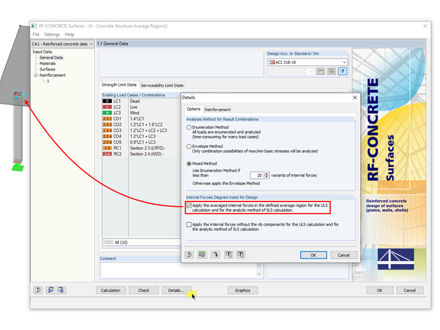
W przypadku obliczeń powierzchni betonowych, składową sił wewnętrznych w postaci żebra można pominąć w obliczeniach SGN i w metodzie analitycznej SGU, ponieważ składowa ta jest już uwzględniona w obliczeniach pręta. W tym celu w oknie dialogowym „Szczegóły“ należy zaznaczyć pole wyboru. Jeżeli nie zostało zdefiniowane żebro, funkcja ta nie jest dostępna.
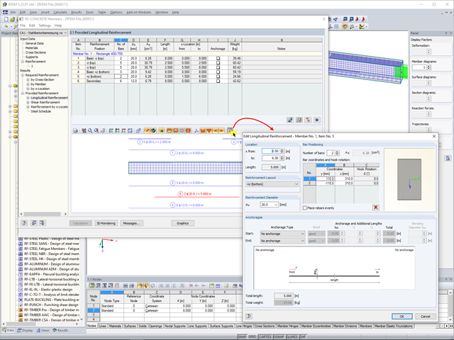
Jeżeli w oknie 1.6 "Zbrojenie" zaznaczona jest opcja "Oblicz rzeczywiste zbrojenie", moduł RF-CONCRETE Members dla RFEM lub CONCRETE dla RSTAB proponują użytkownikowi automatycznie utworzone zbrojenie.
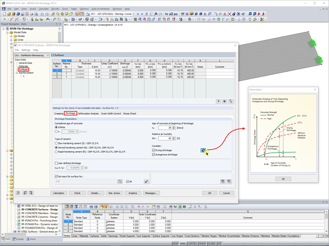
Kriechen und Schwinden des Betons sind Verformungseigenschaften des Betons, welche bei der Bemessung im Grenzzustand der Gebrauchstauglichkeit in der Regel zu berücksichtigen sind.
W programach RFEM 5 i RSTAB 8 można wymiarować fundamenty zgodnie z EN 1992-1-1 i EN 1997-1 w module dodatkowym RF-/FOUNDATION Pro.
In RF-BETON Flächen für RFEM 5 ist es möglich, die Bemessung der Betonflächen mit den geglätteten Schnittgrößen durchzuführen.
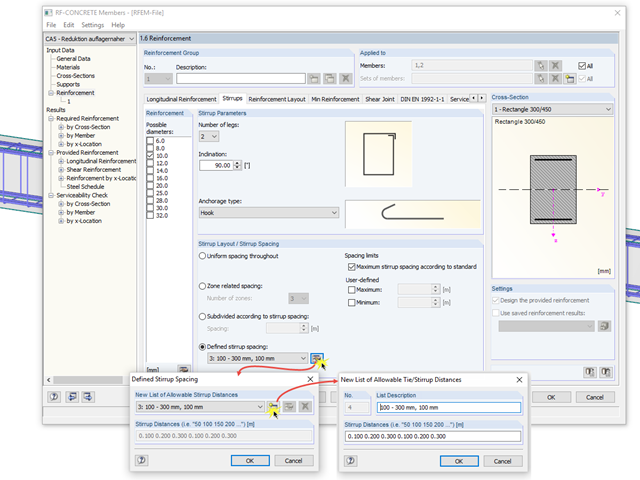
Für die Abdeckung der erforderlichen Querbewehrung ermitteln RF-BETON Stäbe und BETON in Abhängigkeit des vordefinierten Bügeldurchmessers die wirtschaftlichste Querbewehrung als Bewehrungsvorschlag.
Moduł dodatkowy RF-STEEL AISC umożliwia wymiarowanie prętów stalowych zgodnie z normą AISC 360-16. W poniższym artykule technicznym porównano wyniki obliczeń zwichrzenia zgodnie z rozdziałem F i wyniki pochodzące z analizy wartości własnych.
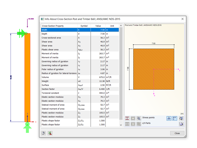
Korzystając z modułu dodatkowego RF-TIMBER AWC możliwe jest wymiarowanie słupów drewnianych zgodnie z metodą ASD według amerykańskiej normy NDS 2018. Dokładne wyznaczenie nośności na ściskanie oraz współczynników redukcyjnych dla prętów drewnianych jest konieczne dla bezpieczeństwa konstrukcji. Poniższy artykuł weryfikuje maksymalne wyboczenie krytyczne w module RF-TIMBER AWC za pomocą równań analitycznych krok po kroku zgodnie z normą NDS 2018, w tym współczynników dostosowania przy ściskaniu, skorygowanej wartości obliczeniowej przy ściskaniu i końcowego stopnia wyboczenia.
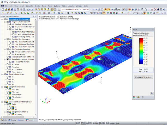
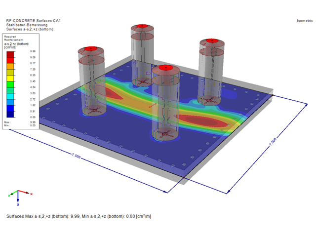
Moduł RF-CONCRETE Surfaces umożliwia wymiarowanie powierzchni z betonu zbrojonego (ściany, stropy, płyty fundamentowe) zgodnie z ACI 318-19 lub CSA A23.3-19. Powszechnym podejściem przy wymiarowaniu płyt jest zastosowanie pasm obliczeniowych do określenia średnich sił wewnętrznych w danym kierunku na szerokości pasma. Metoda ta sprowadza się zasadniczo do analizy elementu dwukierunkowo zbrojonego jako wydzielonych elementów jednokierunkowo zbrojonych, aby określić wymagane zbrojenie wzdłuż danego pasma.
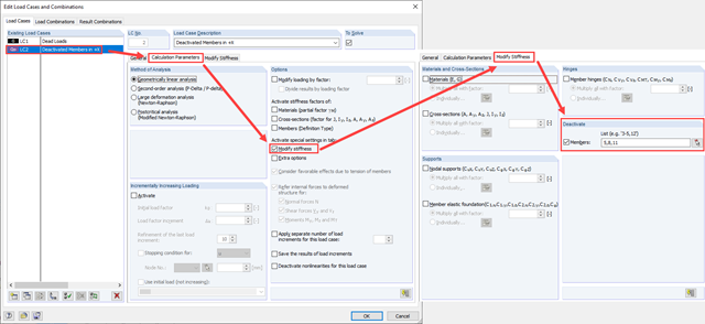
Zarówno analiza drgań własnych, jak i analiza spektrum odpowiedzi przeprowadzane są na układzie liniowym. Jeżeli w modelu występują nieliniowości, podlega on linearyzacji, dzięki czemu elementy nieliniowe nie są brane pod uwagę w dalszej analizie. W praktyce jednak bardzo często wprowadzamy do modeli elementy "tylko rozciągane". W przedstawionym artykule opisano, w jaki sposób można je poprawnie zastąpić dla przeprowadzenia liniowej analizy dynamicznej.