83 Wyniki
Wyświetl wyniki:
Sortuj według:

Podczas obliczania regularnych konstrukcji wprowadzanie danych często nie jest skomplikowane, ale czasochłonne. Oszczędzaj cenny czas dzięki automatycznemu wprowadzaniu danych. W niniejszym przypadku należy uwzględnić kondygnacje domu jako poszczególne etapy budowy. Dane są wprowadzane przy pomocy programu w języku C#, aby użytkownik nie musiał ręcznie wprowadzać elementów poszczególnych pięter.
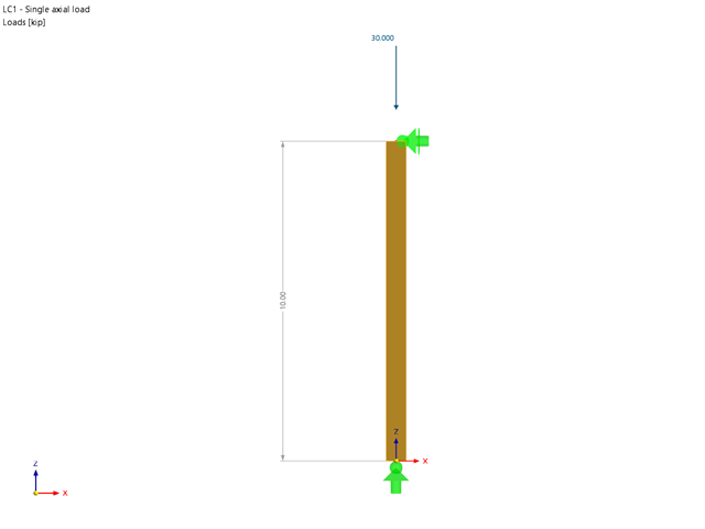
Rozszerzenie Wymiarowanie drewna umożliwia wymiarowanie słupów drewnianych zgodnie ze standardową metodą ASD 2018 NDS. Dokładne wyznaczenie nośności na ściskanie oraz współczynników redukcyjnych dla prętów drewnianych jest konieczne dla bezpieczeństwa konstrukcji. Poniższy artykuł weryfikuje maksymalną wytrzymałość na wyboczenie krytyczną obliczoną w module rozszerzeniowym Wymiarowanie drewna przy użyciu równań analitycznych krok po kroku zgodnie z normą NDS 2018, w tym współczynników dostosowania przy ściskaniu, skorygowanej wartości obliczeniowej na ściskanie i końcowego stopnia wyboczenia.
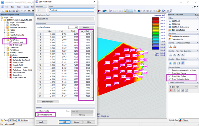
Za pomocą programów RWIND 2 i RFEM 6 można teraz obliczać obciążenia wiatrem na podstawie zmierzonego eksperymentalnie ciśnienia wiatru na powierzchnie. Zasadniczo dostępne są dwie metody interpolacji, umożliwiające rozłożenie ciśnienia mierzonego w izolowanych punktach na powierzchnie. Żądany rozkład ciśnienia można uzyskać za pomocą odpowiedniej metody i ustawień parametrów.
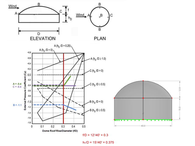
Jeśli chodzi o obciążenia wiatrem konstrukcje budowlane zgodnie z ASCE 7, można znaleźć wiele źródeł, które mogą uzupełnić normy projektowe i pomóc inżynierom w zastosowaniu obciążeń poprzecznych. Jednak inżynierom może być trudniej znaleźć podobne zasoby dla obciążeń wiatrem na konstrukcjach innych niż budynki. W tym artykule omówiono etapy obliczania i przykładania obciążeń wiatrem zgodnie z ASCE 7-22 na okrągłym zbiorniku żelbetowym z dachem w kształcie kopuły.
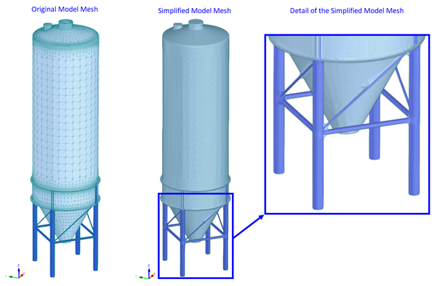
Obliczenia CFD są na ogół bardzo złożone. Dokładne obliczenia przepływu wiatru wokół skomplikowanych konstrukcji są bardzo czasochłonne i kosztowne. W wielu zastosowaniach inżynierskich wysoka dokładność nie jest wymagana, a nasz program CFD RWIND 2 pozwala w takich przypadkach uprościć model konstrukcji i znacznie zredukować koszty. W tym artykule odpowiedzi na niektóre pytania dotyczące uproszczenia.
Zgodność z przepisami budowlanymi, takimi jak Eurokod, jest niezbędna dla zapewnienia bezpieczeństwa, integralności konstrukcji i trwałości budynków i konstrukcji. Obliczeniowa mechanika płynów (CFD) odgrywa istotną rolę w tym procesie, symulując zachowanie płynów, optymalizując projekty i pomagając architektom i inżynierom w spełnieniu wymagań Eurokodu związanych z analizą obciążenia wiatrem, wentylacją naturalną, bezpieczeństwem pożarowym i efektywnością energetyczną. Integrując CFD z procesem projektowania, profesjonaliści mogą tworzyć bezpieczniejsze, wydajniejsze i zgodne z przepisami budynki, które spełniają najwyższe standardy konstrukcyjne i projektowe w Europie.
Celem zastosowania programów RFEM 6 i Blender z rozszerzeniem Bullet Constraints Builder jest uzyskanie graficznej reprezentacji zawalenia się modelu na podstawie rzeczywistych danych dotyczących właściwości fizycznych. Program RFEM 6 służy jako źródło geometrii i danych do symulacji. Jest to kolejny przykład, dlaczego ważne jest, aby nasze programy utrzymywać jako tak zwane BIM Open, aby umożliwić współpracę między różnymi dziedzinami oprogramowania.
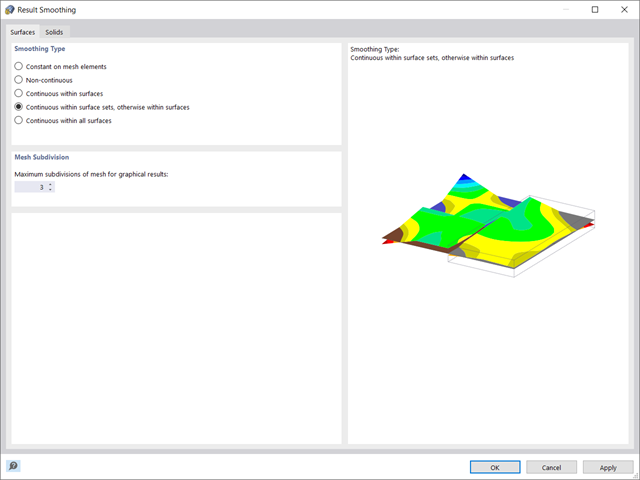
W programie RFEM 6 wyniki dla węzłów siatki ES są określane przy użyciu metody elementów skończonych. Aby rozkład sił wewnętrznych, odkształceń i naprężeń był ciągły, wartości węzłowe są uśredniane w procesie interpolacji. W tym artykule przedstawimy i porównamy różne typy uśredniania, które w tym celu można zastosować.
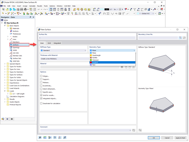
Powierzchnie w modelach budynków mogą mieć różne rozmiary i kształty. W programie RFEM 6 można uwzględnić wszystkie powierzchnie, ponieważ program umożliwia definiowanie różnych materiałów i grubości, a także powierzchni o różnej sztywności i typie geometrii. W tym artykule skupiono się na czterech z następujących typów powierzchni: obrócony, przycięty, bez grubości i przeniesienia obciążenia.
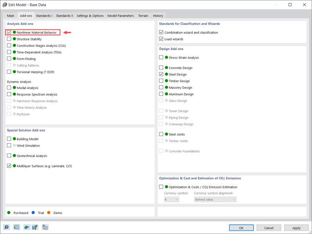
Rozszerzenie Nieliniowe zachowanie materiału umożliwia uwzględnienie nieliniowości materiałowych w programie RFEM 6. Ten artykuł zawiera przegląd dostępnych nieliniowych modeli materiałowych, które są dostępne po aktywowaniu tego rozszerzenia w danych bazowych modelu.
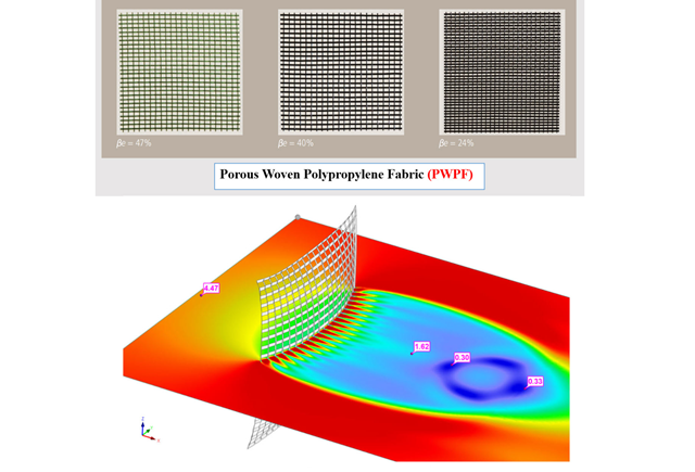
W obliczeniowej mechanice płynów (CFD) można modelować złożone powierzchnie, które nie są całkowicie stałe, używając porowatego i przepuszczalnego medium. W świecie rzeczywistym mogą to być na przykład wiatrochrony, siatki druciane, perforowane fasady i okładziny, żaluzje, przęsła (stosy poziomych walców) i tak dalej.
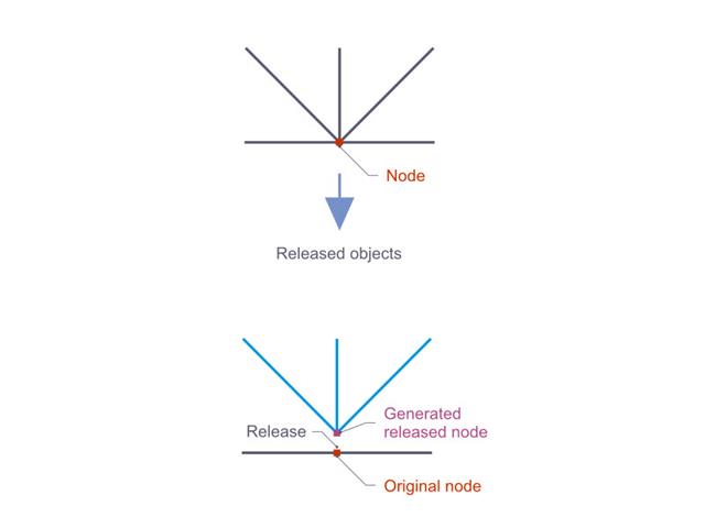
Zwolnienia węzłowe są to specjalne obiekty w programie RFEM 6, które umożliwiają konstrukcyjne odłączenie obiektów dołączonych do węzła. Zwolnienie jest sterowane przez warunki typu zwolnienia, które również mogą mieć właściwości nieliniowe. W tym artykule przedstawiono definicję zwolnień węzłowych na praktycznym przykładzie.
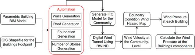
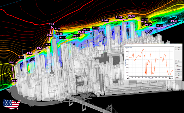
W artykule tym opracowano nowatorskie podejście do generowania modeli CFD na poziomie miejscowości poprzez połączenie modelowania informacji o budynku (BIM) i systemów informacji geograficznej (GIS) w celu zautomatyzowania generowania trójwymiarowego modelu terenu o wysokiej rozdzielczości, który zostanie wykorzystany jako dane wejściowe dla cyfrowego tunelu aerodynamicznego z wykorzystaniem RWIND.
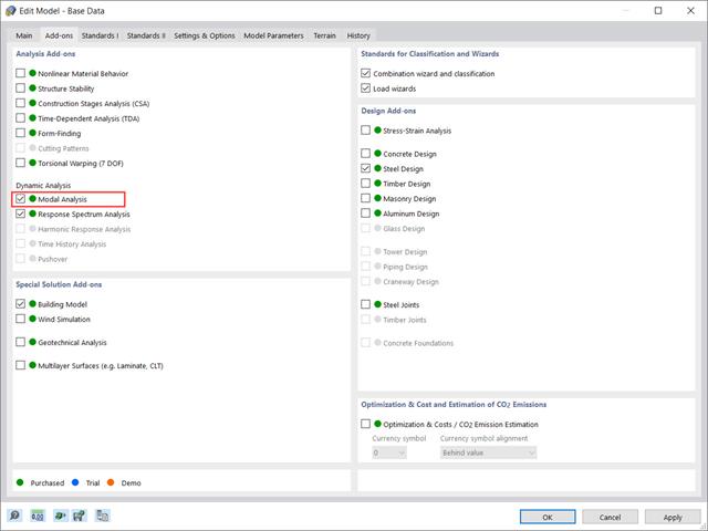
Rozszerzenie „Analiza modalna” w RFEM 6 umożliwia przeprowadzanie analizy modalnej układów konstrukcyjnych, określając w ten sposób wartości drgań własnych, takie jak częstotliwości drgań własnych, kształty modalne, masy modalne i efektywne modalne współczynniki masy. Wyniki te można wykorzystać do obliczeń drgań, a także do dalszych analiz dynamicznych (na przykład obciążenia widmem odpowiedzi).
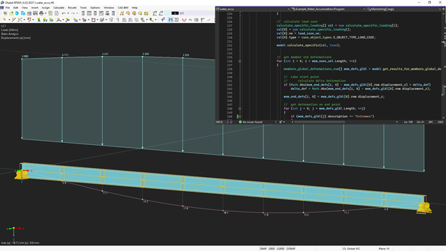
API dla RFEM 6, RSTAB 9 i RSECTION opiera się na koncepcji usług sieciowych (Webservice). Aby zapoznać się z tematem, w poniższym artykule omawiamy kolejny przykład w języku C#.
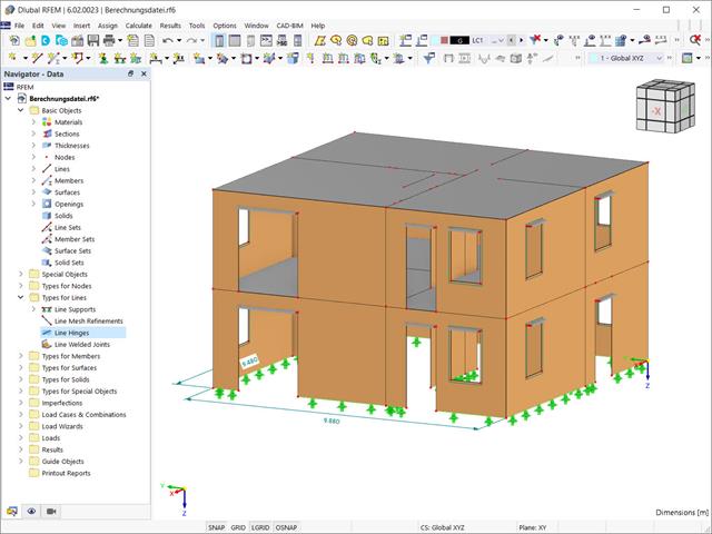
Przy użyciu specjalnego przegubu liniowego dostępnego w programie RFEM 6 można poprawnie uwzględnić podczas modelowania właściwości połączenia płyty żelbetowej ze ścianą murowaną. Z tego artykułu dowiesz się, jak zdefiniować ten typ przegubu na praktycznym przykładzie.
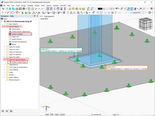
W tym artykule opisano, jak tworzyć kontakty między dwiema lub większą liczbą równoległych powierzchni poprzez kontrolowanie przenoszenia sił między nimi.
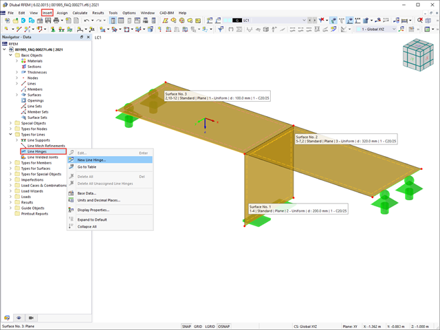
W tym artykule pokażemy, jak prawidłowo uwzględnić połączenie między powierzchniami stykającymi się na jednej linii za pomocą przegubów liniowych w programie RFEM 6.
W tym artykule podsumowano zalety pracy ze sparametryzowanymi modelami w programach RFEM 6 i RSTAB 9.

W programie RFEM 6 możliwe jest definiowanie spoin liniowych na liniach między powierzchniami i obliczanie naprężeń w spoinie za pomocą rozszerzenia Analiza naprężeniowo-odkształceniowa. Z tego artykułu dowiesz się, jak to zrobić.
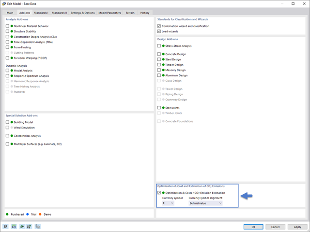
Z tego artykułu dowiesz się, jak oszacować emisję CO₂ w programie RFEM 6/RSTAB 9.
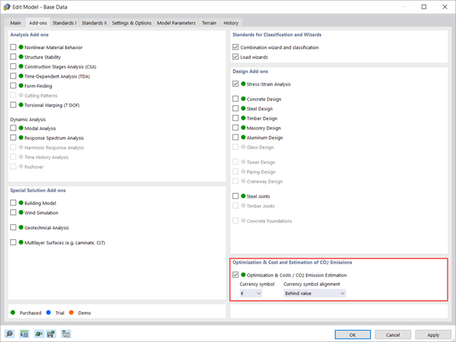
Z tego artykułu dowiesz się, jak za pomocą rozszerzenia Optymalizacja i koszty/Szacowanie emisji CO₂ do oszacowania kosztów modelu. Ponadto pokazano, w jaki sposób można zoptymalizować parametry w oparciu o minimalny koszt podczas pracy z modelami i blokami sparametryzowanymi.
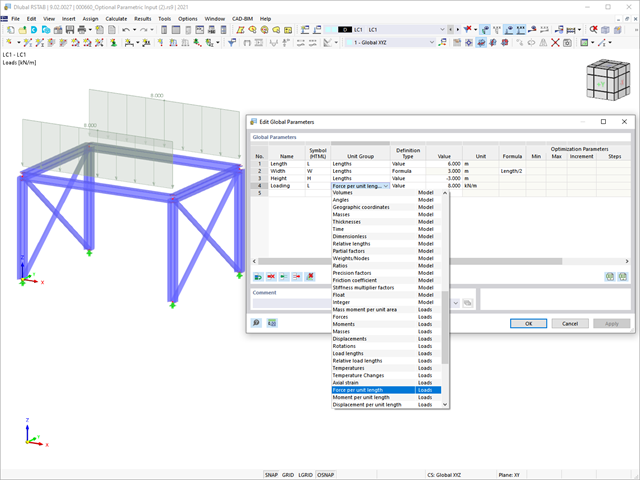
Z tego artykułu dowiesz się, jak zoptymalizować parametry globalne w programie RFEM 6 w zależności od różnych aspektów.
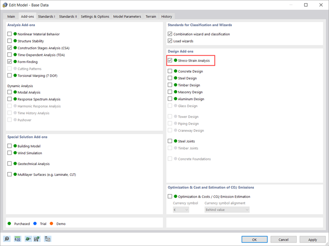
W tym artykule pokazano, jak zarządzać danymi wejściowymi dla konfiguracji obliczeń prętów i powierzchni w rozszerzeniu Analiza naprężeniowo-odkształceniowa.
W tym artykule omówiono wyniki analizy geotechnicznej oraz ich graficzne i tabelaryczne przedstawienie w programie RFEM 6.
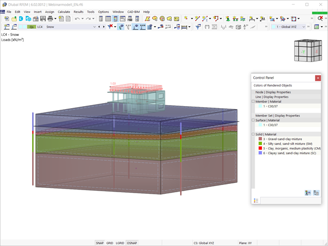
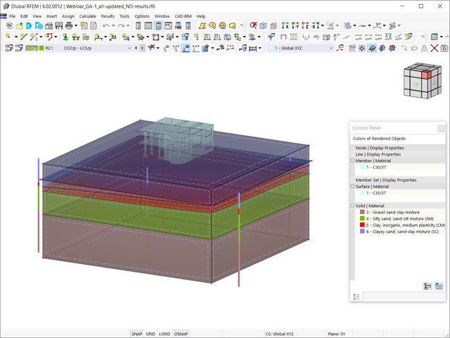
Biorąc pod uwagę, że realistyczne określenie warunków gruntowych znacząco wpływa na jakość analizy statyczno-wytrzymałościowej budynków, w programie RFEM 6 dostępne jest rozszerzenie Analiza geotechniczna, które umożliwia określenie konturu glebowego do analizy.
Sposób udostępnienia danych uzyskanych z badań polowych w rozszerzeniu i wykorzystania właściwości z próbek gruntu do określenia masywów gruntu, które mają być przedmiotem zainteresowania, został omówiony w artykule z Bazy informacji „Tworzenie bryły gruntowej na podstawie próbek gruntu w programie RFEM 6”. W tym artykule omówiono natomiast procedurę obliczania osiadań i parcia gruntu dla budynku żelbetowego.
Sposób udostępnienia danych uzyskanych z badań polowych w rozszerzeniu i wykorzystania właściwości z próbek gruntu do określenia masywów gruntu, które mają być przedmiotem zainteresowania, został omówiony w artykule z Bazy informacji „Tworzenie bryły gruntowej na podstawie próbek gruntu w programie RFEM 6”. W tym artykule omówiono natomiast procedurę obliczania osiadań i parcia gruntu dla budynku żelbetowego.

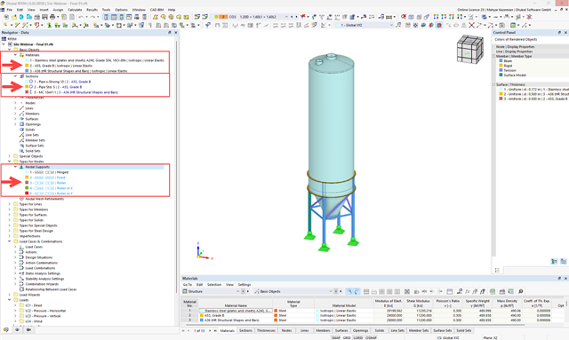
Jakość analizy statyczno-wytrzymałościowej budynków jest dużo lepsza, gdy można uwzględnić warunki gruntowe w sposób możliwie najbardziej realistyczny. W programie RFEM 6 można realistycznie określić kontur glebowy do analizy za pomocą rozszerzenia Analiza geotechniczna. Ten dodatek można aktywować w danych bazowych modelu, jak pokazano na rysunku 01.

Zaletą modułu dodatkowego RFEM 6 Steel Joints jest możliwość analizy połączeń stalowych przy użyciu modelu MES, dla którego modelowanie przebiega w pełni automatycznie w tle. Elementy składowe złącza stalowego, które kontrolują modelowanie, można wprowadzić, definiując je ręcznie lub korzystając z dostępnych szablonów w bibliotece. Ta ostatnia metoda została opisana w poprzednim artykule z Bazy wiedzy zatytułowanym „Definiowanie komponentów połączenia stalowego przy użyciu biblioteki”. Definiowanie parametrów do wymiarowania połączeń stalowych jest tematem artykułu w bazie wiedzy „Projektowanie połączeń stalowych w RFEM 6”.
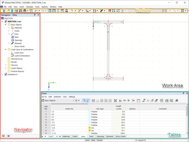
RSECTION 1 to program samodzielny do określania właściwości przekrojów zarówno dla przekrojów cienkościennych, jak i masywnych, a także do przeprowadzania analizy naprężeń. Ponadto program może być połączony zarówno z RFEM, jak i RSTAB: przekroje z programu RFEM/RSTAB są dostępne w bibliotekach programu RFEM/RSTAB, a siły wewnętrzne z programu RFEM/RSTAB można zaimportować do programu RSECTION.

Rozszerzenie Projektowanie konstrukcji aluminiowych dla RFEM 6 wymiaruje pręty aluminiowe ze względu na stan graniczny nośności i użytkowalności zgodnie z Eurokodem 9. Ponadto możliwe jest wymiarowanie zgodnie z ADM 2020 (norma amerykańska).