44 Wyniki
Wyświetl wyniki:
Sortuj według:

W tym artykule wyjaśniono różne metody dostępne w rozszerzeniu Analiza modalna, służące do określania liczby postaci własnych.

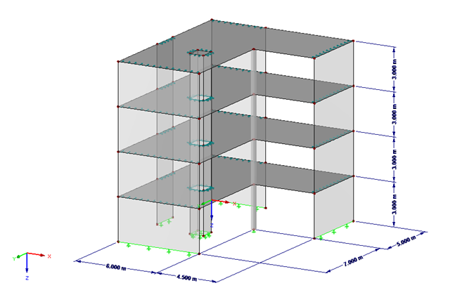
Ocena przemieszczenia kondygnacji w budynku jest kluczowa dla zapewnienia zadowalających parametrów konstrukcyjnych poprzez ograniczenie przemieszczenia kondygnacji. Nadmierne znoszenie może powodować niestateczność systemu i powodować uszkodzenia elementów niekonstrukcyjnych, takich jak ściany działowe. W tym artykule opisano procedurę wyznaczania przemieszczeń międzykondygnacyjnych zgodnie z ASCE 7-22 i rozszerzeniem Model budynku w programie RFEM 6.

Norma ASCE 7-22 [1], rozdz. 12.9.1.6 określa, kiedy efekty P-delta powinny być uwzględniane podczas przeprowadzania analizy modalnego spektrum odpowiedzi dla obliczeń sejsmicznych. W NBC 2020 [2], Wys. 4.1.8.3.8.c jedynie w niewielkim stopniu wymaga uwzględnienia przechyłów spowodowanych interakcją obciążeń grawitacyjnych z konstrukcją odkształconą. Z tego względu podczas przeprowadzania analizy sejsmicznej mogą wystąpić sytuacje, w których efekty drugiego rzędu, znane również jako P-delta, muszą zostać uwzględnione.

W artykule przedstawiono podstawowe pojęcia z zakresu dynamiki konstrukcji i ich roli w projektowaniu konstrukcji sejsmicznych. Duży nacisk kładzie się na wyjaśnienie aspektów technicznych w zrozumiały sposób, aby tematyka była zrozumiała dla czytelników bez dużej wiedzy technicznej.

Artykuł 4.1.8.7 kanadyjskich przepisów budowlanych (NBC) 2020 zawiera jasną procedurę dotyczącą metod analizy trzęsień ziemi. Metoda bardziej zaawansowana, a mianowicie metoda analizy dynamicznej opisana w rozdziale 4.1.8.12, powinna być stosowana dla wszystkich typów konstrukcji, z wyjątkiem tych, które spełniają kryteria podane w 4.1.8.7. W przypadku pozostałych konstrukcji, może być stosowana nieco prostsza metoda równoważnych sił statycznych (ESFP), opisana w rozdziale 4.1.8.11.
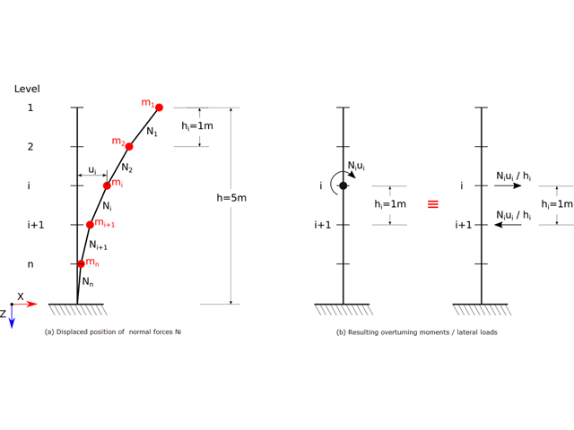
Zgodnie z normami EN 1998-1 sekcje 2.2.2 i 4.4.2.2 do obliczeń stanu granicznego nośności należy przeprowadzić obliczenia z uwzględnieniem teorii drugiego rzędu (efekt P-Δ). Efekt ten nie musi być uwzględniany tylko w przypadku, gdy współczynnik wrażliwości międzykondygnacyjnej jest mniejszy niż 0,1.
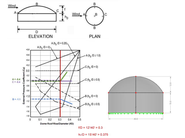
Jeśli chodzi o obciążenia wiatrem konstrukcje budowlane zgodnie z ASCE 7, można znaleźć wiele źródeł, które mogą uzupełnić normy projektowe i pomóc inżynierom w zastosowaniu obciążeń poprzecznych. Jednak inżynierom może być trudniej znaleźć podobne zasoby dla obciążeń wiatrem na konstrukcjach innych niż budynki. W tym artykule omówiono etapy obliczania i przykładania obciążeń wiatrem zgodnie z ASCE 7-22 na okrągłym zbiorniku żelbetowym z dachem w kształcie kopuły.

Zarówno analiza drgań własnych, jak i analiza spektrum odpowiedzi przeprowadzane są na układzie liniowym. Jeżeli w modelu występują nieliniowości, podlega on linearyzacji, dzięki czemu elementy nieliniowe nie są brane pod uwagę w dalszej analizie. Mogą to być na przykład pręty rozciągane, podpory nieliniowe lub przeguby nieliniowe. W tym artykule pokazano, w jaki sposób można nimi zarządzać w analizie dynamicznej.
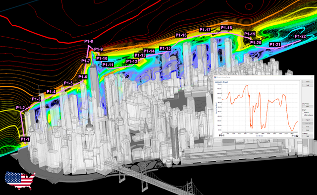
Zgodność z przepisami budowlanymi, takimi jak Eurokod, jest niezbędna dla zapewnienia bezpieczeństwa, integralności konstrukcji i trwałości budynków i konstrukcji. Obliczeniowa mechanika płynów (CFD) odgrywa istotną rolę w tym procesie, symulując zachowanie płynów, optymalizując projekty i pomagając architektom i inżynierom w spełnieniu wymagań Eurokodu związanych z analizą obciążenia wiatrem, wentylacją naturalną, bezpieczeństwem pożarowym i efektywnością energetyczną. Integrując CFD z procesem projektowania, profesjonaliści mogą tworzyć bezpieczniejsze, wydajniejsze i zgodne z przepisami budynki, które spełniają najwyższe standardy konstrukcyjne i projektowe w Europie.
Analiza spektrum odpowiedzi jest jedną z najczęściej stosowanych metod obliczeniowych w przypadku obciążenia trzęsieniem ziemi. Metoda ta ma wiele zalet, a najważniejsza z nich to możliwość znacznego uproszczenia obliczeń. Skomplikowany charakter obciążenia jakim jest trzęsienie ziemi jest upraszczany do postaci, która umożliwia przeprowadzenie analizy o rozsądnym stopniu pracochłonności. Wadą metody jest natomiast to, że w wyniku tego uproszczenia traci się część informacji o obciążeniu. Sposobem na zniwelowanie tego ograniczenia może być zastosowanie równoważnej kombinacji liniowej podczas łączenia odpowiedzi modalnych. W poniższym artykule wyjaśniono to bardziej szczegółowo na konkretnym przykładzie.
Modalny współczynnik istotności jest wynikiem analizy stateczności liniowej i opisuje jakościowo stopień udziału poszczególnych prętów w określonym kształcie drgań.
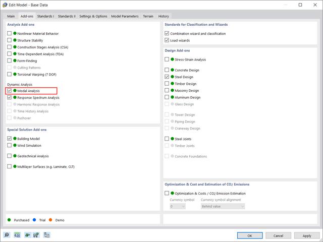
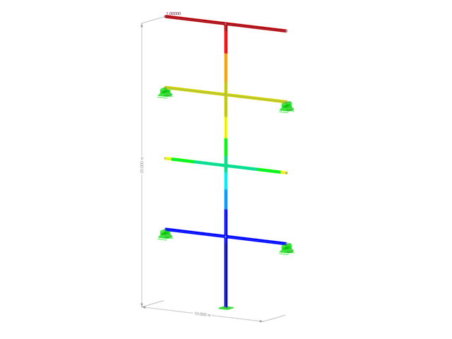
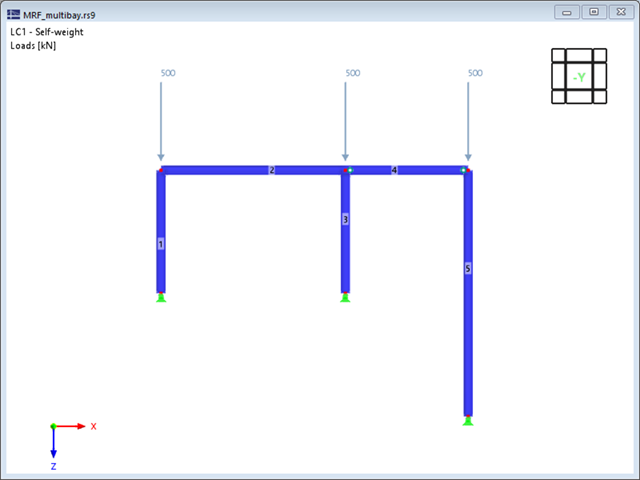
Rozszerzenie „Analiza modalna” w RFEM 6 umożliwia przeprowadzanie analizy modalnej układów konstrukcyjnych, określając w ten sposób wartości drgań własnych, takie jak częstotliwości drgań własnych, kształty modalne, masy modalne i efektywne modalne współczynniki masy. Wyniki te można wykorzystać do obliczeń drgań, a także do dalszych analiz dynamicznych (na przykład obciążenia widmem odpowiedzi).
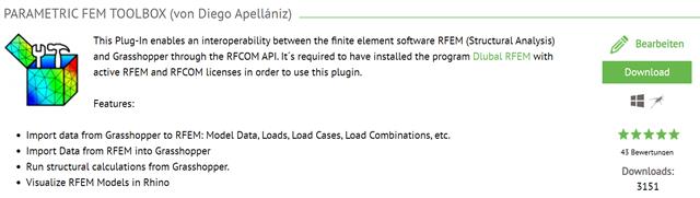
W tym artykule opisano rozwój Parametric FEM Toolbox i niektóre z możliwych przepływów pracy przy użyciu tego nowego narzędzia.

Analiza dynamiczna w RFEM 6 i RSTAB 9 jest podzielona na kilka rozszerzeń. Rozszerzenie Analiza modalna jest niezbędne dla wszystkich innych rozszerzeń do analizy dynamicznej, ponieważ przeprowadza analizę drgań własnych dla modeli prętów, powierzchni i brył.

Analiza modalna jest punktem wyjścia do analizy dynamicznej układów konstrukcyjnych. Można ją wykorzystać do określenia wartości drgań własnych, takich jak częstotliwości drgań własnych, kształty drgań własnych, masy modalne i efektywne współczynniki masy modalnej. Wynik ten może zostać wykorzystany do obliczeń drgań oraz do dalszych analiz dynamicznych (na przykład obciążenia widmem odpowiedzi).
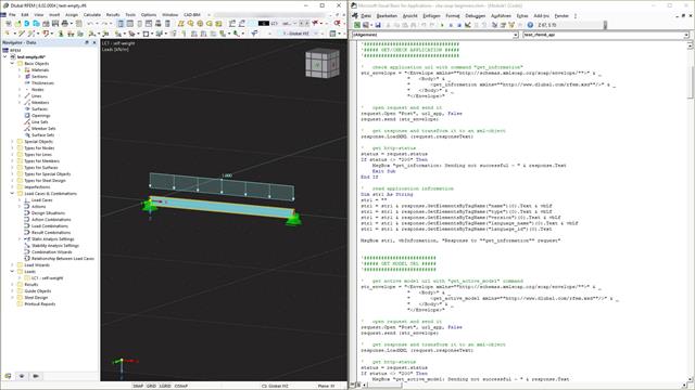
Webservice to komunikacja między maszynami i programami. Komunikacja ta odbywa się za pośrednictwem sieci i dlatego może być wykorzystywana przez dowolny program, który może wysyłać i odbierać ciągi znaków za pośrednictwem protokołu HTTP. Programy RFEM 6 i RSTAB 9 zapewniają interfejs oparty na tych wieloplatformowych usługach sieciowych. Ten tutorial pokazuje podstawy korzystania z języka programowania VBA.
Wraz z programami do analizy statyczno-wytrzymałościowej RFEM 6, RSTAB 9, RSECTION 1 i RWIND 2, Dlubal Software przedstawia nową generację programów do analizy statyczno-wytrzymałościowej. Getreu dem Motto „Statik, die Spaß macht…“ werden den Anwendern universelle Werkzeuge in die Hand gegeben, mit denen alle Anforderungen in der Tragwerksplanung bewältigt werden können. Was sich sonst noch bei Dlubal Software Neues getan hat, erfahren Sie in diesem Artikel.
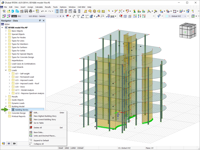
W programie RFEM 6 analizę sejsmiczną można przeprowadzić za pomocą modułów dodatkowych Analiza modalna i Analiza spektrum odpowiedzi. Zaraz po zakończeniu analizy spektralnej za pomocą rozszerzenia Model budynku można wyświetlić oddziaływania kondygnacji, przemieszczenia kondygnacji i siły w ścianach usztywniających.
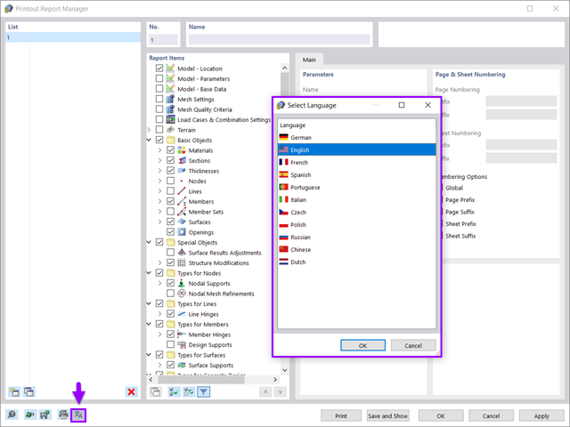
Wszystkie dane w programie RFEM 6 można udokumentować w wielojęzycznym raporcie. Protokół wydruku jest nowoczesny i zoptymalizowany w porównaniu z poprzednią generacją programu (RFEM 5). W tym artykule technicznym przedstawiono niektóre z najważniejszych funkcji.

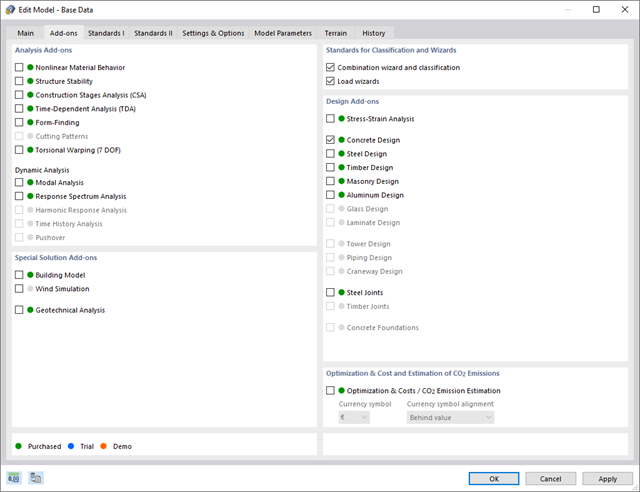
Analiza sejsmiczna w programie RFEM 6 jest możliwa przy użyciu rozszerzeń analizy modalnej i analizy spektrum odpowiedzi. Ogólna koncepcja analizy sejsmicznej w programie RFEM 6 opiera się na utworzeniu przypadku obciążenia do analizy modalnej lub analizy spektrum odpowiedzi. Grupy norm dla tych analiz są ustawiane w zakładce Normy II w oknie Dane podstawowe modelu.
Nowa generacja oprogramowania RFEM to intuicyjny, wydajny i łatwy w obsłudze program 3D MES, który spełnia wszystkie najnowsze wymagania w zakresie modelowania, obliczeń i wymiarowania konstrukcji. Nowoczesna koncepcja projektowa, a także wprowadzenie nowych funkcji, czynią program jeszcze bardziej innowacyjnym i przyjaznym dla użytkownika. Poniżej omówiono główne różnice między programem RFEM 6 a jego poprzednią wersją, RFEM 5.
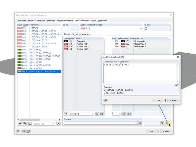
Beim Dialog für die Syntax-Eingabe der Kombinatorik von Last- beziehungsweise Ergebniskombinationen handelt es sich um einen nicht modalen Dialog. Das heißt, dass nach dem Öffnen dieses Dialoges Eingaben auch außerhalb des Dialoges möglich sind. Für die Syntax-Eingabe bedeutet dies, dass der Dialog mit dem Bearbeitungsfeld parallel zum Dialog "Lastfälle und Kombinatorik bearbeiten" geöffnet sein kann.
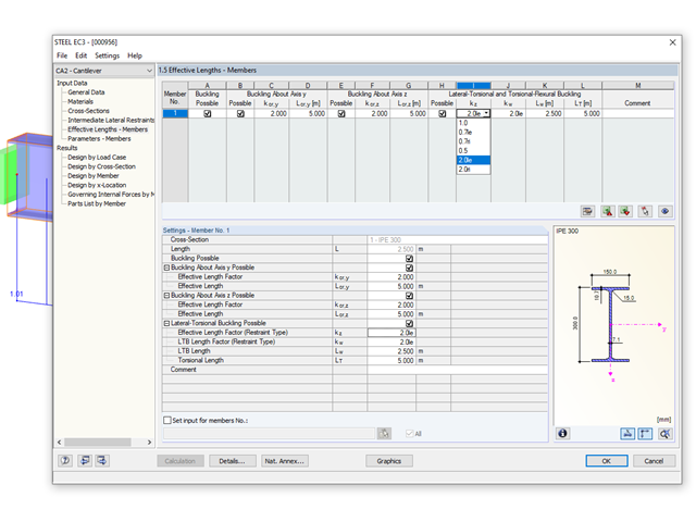
Die Stab-Randbedingungen beeinflussen das ideale Verzweigungsmoment bei Biegedrillknicken Mcr in entscheidender Weise. Für die Ermittlung wird im Programm ein ebenes Modell mit vier Freiheitsgraden verwendet. Die entsprechenden Beiwerte kz und kw können hierbei für normkonforme Querschnitte individuell definiert werden. Damit lassen sich die Freiheitsgrade beschreiben, die durch die Lagerungsbedingungen an den beiden Stabenden vorliegen.
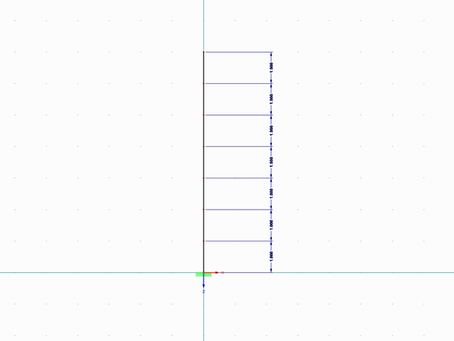
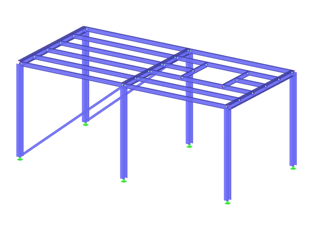
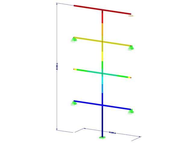
Mit RF-/DYNAM Pro Ersatzlasten ist es möglich, eine Ersatzlastberechnung anhand des multimodalen Antwortspektren-Verfahrens zu durchzuführen. Im dargestellten Beispiel wurde dies für einen Mehrmassenschwinger durchgeführt.
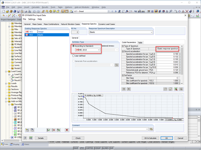
W normie kanadyjskiej NBC 2015 rozdział 4.1.8.7 określa w sposób przejrzysty procedury dla różnych metod analizy sejsmicznej obiektów budowlanych. Metoda bardziej zaawansowana, a mianowicie metoda analizy dynamicznej opisana w rozdziale 4.1.8.12, powinna być stosowana dla wszystkich typów konstrukcji, z wyjątkiem tych, które spełniają kryteria podane w 4.1.8.7. W przypadku pozostałych konstrukcji, może być stosowana nieco prostsza metoda równoważnych sił statycznych (ESFP), opisana w rozdziale 4.1.8.11.
Za pomocą analizy modalnej w programie DYNAM Pro - Vibrations Forced można wyznaczyć rozwiązanie dla stanu ustalonego konstrukcji poddanej drganiom wymuszonym harmonicznie. Jest to korzystne, jeżeli interesuje nas tylko stan ustalony drgań konstrukcji. Wówczas zamiast pełnego rozwiązania równania ruchu konstrukcji, wystarczy wyświetlić przypadek szczególny.
Analiza spektrum odpowiedzi jest jedną z najczęściej stosowanych metod obliczeniowych w przypadku obciążenia trzęsieniem ziemi. Metoda ta ma wiele zalet, a najważniejsza z nich to możliwość znacznego uproszczenia obliczeń. Skomplikowany charakter obciążenia jakim jest trzęsienie ziemi jest upraszczany do postaci, która umożliwia przeprowadzenie analizy o rozsądnym stopniu pracochłonności. Wadą metody jest natomiast to, że w wyniku tego uproszczenia traci się część informacji o obciążeniu. Sposobem na zniwelowanie tego ograniczenia może być zastosowanie równoważnej kombinacji liniowej podczas łączenia odpowiedzi modalnych. W poniższym artykule wyjaśniono to bardziej szczegółowo na konkretnym przykładzie.
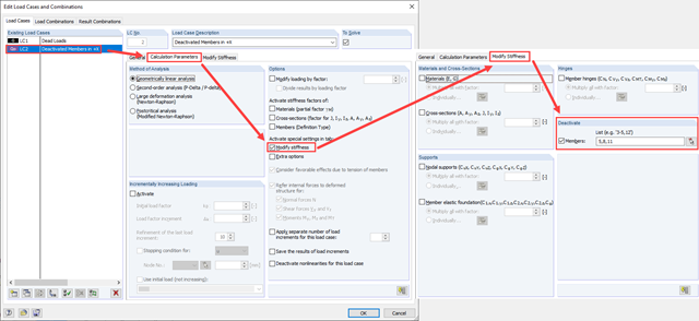
Zarówno analiza drgań własnych, jak i analiza spektrum odpowiedzi przeprowadzane są na układzie liniowym. Jeżeli w modelu występują nieliniowości, podlega on linearyzacji, dzięki czemu elementy nieliniowe nie są brane pod uwagę w dalszej analizie. W praktyce jednak bardzo często wprowadzamy do modeli elementy "tylko rozciągane". W przedstawionym artykule opisano, w jaki sposób można je poprawnie zastąpić dla przeprowadzenia liniowej analizy dynamicznej.
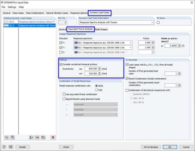
W celu uwzględnienia niedokładności dotyczących położenia mas w analizie spektrum odpowiedzi, normy do obliczeń sejsmicznych określają zasady, które muszą być stosowane zarówno w uproszczonej, jak i multimodalnej analizie spektrum odpowiedzi. Reguły te opisują następującą ogólną procedurę: masa kondygnacji musi zostać przesunięta o pewien mimośród, co powoduje powstanie momentu skręcającego.
Podczas wprowadzania i przenoszenia obciążeń poziomych, takich jak wiatr lub obciążenia sejsmiczne, w modelach 3D pojawiają się coraz większe trudności. Aby uniknąć takich problemów, niektóre normy (np. ASCE 7, NBC) wymagają uproszczenia modelu za pomocą przepon, które rozkładają obciążenia poziome na elementy konstrukcyjne przenoszące obciążenia, ale nie mogą samodzielnie przenosić zginania (tzw. „Przepona”).