


The Dlubal customer Moses Structural Engineers Inc. from Toronto, Canada wrote a pre-design feasibility report, worked in 3D to develop the preliminary geometry and detailed the design with supply, shipping, and installation in mind.
The engineers from Moses also developed the erection sequencing plan for the contractor and refined the shop details and drawings. The structural analysis of the steel-timber structure was carried out with RSTAB.
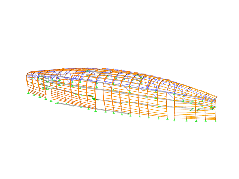
Structure of the Timber Veil
The structure consists of 24 curved glued-laminated members with varying lengths. The members are supported at the base with a pinned connection and fixed at the top by means of a tubular steel structure to the reinforced concrete structure of the stadium. Additionally, the steel diagonals stiffen the structure in the lateral directions. The curved beams are connected horizontally with multiple, smaller glued-laminated beams.
The elegant timber veil has received numerous awards including:
- 2014 Wood Design Award, Ontario Wood WORKS!
- 2014 North American Citation, Wood Design Award
- 2015 Award of Merit – Urban Elements, Ottawa Urban Design Awards
| Client | City of Ottawa / Ottawa Sports and Entertainment Group (OSEG) |
| Architect | CannonDesign www.cannondesign.com |
| Structural Engineering | Moses Structural Engineers Inc. & Halsall Toronto, Canada www.mosesstructures.com |


