


In this article, the most frequent forms of fin plate connections will be shown first, their advantages and disadvantages will be then specified and some explained in detail. Beam to column connections are no further considered, even if they are possible in principle. Furthermore, operational questions should not be neglected. Unfortunately, it happens, when designing steel connections, that the practicability of the connection is not or insufficiently taken into account. Therefore, these possible issues should also be discussed in this article.
In the second part of this article, the calculation and design of fin plate connections according to EN 1993-1-8 [1] will be shown and explained with an example calculated with RF-/JOINTS Steel - Pinned. This article focuses on some designs which are sometimes skipped in design practice. There are many reason for this, the two most frequently are probably the following: The calculation should not be too complex, because it is, as is well-known, "only" about a connection of a secondary beam. Or the designing engineer lacks knowledge about the necessity of one or other design.
The present article should explain the necessity of one design or the other. Finally, in the event of damage, the spurious argument "It has always worked without this design in the past!" will not be very helpful. When performing design, it becomes obvious very quickly how complex it is to design a pinned fin plate connection and how useful a design program like RF-JOINTS Steel - Pinned can be to enable an economical design according to the relevant standards within a reasonable processing time.
In the last section, it will be shown which big disadvantage it is to use fin plate connections and other pinned connections: the often considerable reduction of the critical buckling moment. Most pinned connections and in particular fin plate connections cannot be considered as lateral and torsional restraints, which may lead to a considerable reduction in resistance for beams at stability risk.
Design of Fin Plate Connections
In this section, the most common forms of fin plate connections as beam-to-beam connections will be shown and evaluated with regard to their advantages and disadvantages in calculation and design, as well as in manufacture and assembly. The points mentioned only represent suggestions and make no claim to completeness.
Basically, fin plate connections can be used both as beam to column connections and beam to beam connections whereas beam to column connections will not be discussed in any further detail here. In most cases, other pinned connection types are more favorable for beam to column connections.
The main problem with fin plate connections during assembly is that it is impossible to specifically compensate for manufacturing tolerances such as overlength or short lengths of the beam, as is possible with short end plate connections and double angle connections. The beams are here specifically manufactured with a short length according to the maximum tolerance which corresponds to the standard. The short length thus obtained can be then offset on-site with supplied backing plates.
The fact that this method is not possible with fin plate connections ensures that they should not be arranged between two columns, because it may happen that the beam can only be assembled by force. Apart from this fact that the assemblers have problems with it, effects due to restraint are introduced to the structural system which should be actually avoided.
A big advantage of fin plate connections is, in general, the lower fragmented structure compared with most other pinned connection types. No small parts are necessary except bolts.
In the following, the two most common types of fin plate connections will be shown as beam to beam connection. This is regarded as a connection with a "long" or "short" fin plate.
Beam-to-beam connection with a "long" fin plate:
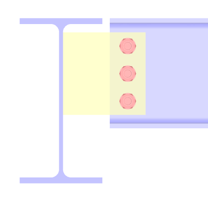
Connections with "long" fin plate are characterized by the fact that no notching is necessary in the connected beam which results in a long fin plate. The two main benefits of this connection type are firstly probably less work in the workshop, because no complex manufactured notching is necessary and secondly the fact that no problems are to be expected when inserting the single beam during the assembly of the beam.
The major disadvantage of this connection type is the fact that it is often far from a lateral and torsional restraint. If lateral-torsional buckling is possible for this beam, it is important to consider the small torsional rigidity of the connection when designing the beam. Since the structural design of steel structures is often performed by a different person than the connection designs, it may lead to problems.
Since the fin plate is also welded to one or both flanges of the main beam when using this type of connection, a barrier of sorts is created. When using hot-dipped structures, this results in additional drillings and cutouts in the fin plate, so that the liquid zinc can drain off when drawn from the zinc bath. Whether the designing engineer has to take this into account, depends on the contract concluded. In structural analysis or design, these additional openings are usually negligible.
Due to the big eccentricity for this connection type, bigger plate thicknesses for the fin are quickly necessary. This, in turn, results in the fact that the welds have to be designed to be very strong, because they should have a bigger ultimate limit state than the connected plate to ensure ductile structural component behavior. It is important to keep in mind here that for fillet welds with the weld root 6 mm and more, it is necessary to weld in multiple layers. The connection thus becomes quickly uneconomical with regard to material and production.
Beam-to-beam connection with a "short" fin plate:
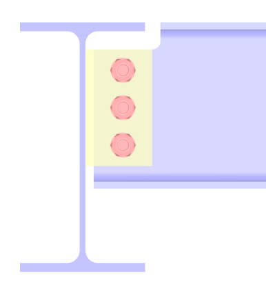
This connection type has all advantages of the configuration with a "long" fin plate, with the exception of a guaranteed, unproblematic assembly of the single beam. For smaller beam spacings, it may happen that the single beam cannot be inserted to the place of installation.
However, since working platforms and catwalks are often pre-assembled on the ground and then inserted in and installed at the place of installation as a whole or in large parts (assembly), the case of inserting a single beam and experiencing related problems rarely occurs. In any event, the planning engineer and/or designer should familiarize himself with the assembly technology of the executing company.
An additional advantage of this option with "short" fin plate is the generally rather small connection eccentricity, which often results in more economical results than the option with "long" fin.
A disadvantage of this connection type is the usually necessary notching of the secondary beam, which results in certain cases in two or even three problems. First of all, the additional effort in production should be mentioned here, which does hardly apply to modern workshops.
The second problem is the lower beam resistance in the notched area. Additional designs are necessary here, which become also the governing designs in some cases. This is particularly the case if notches are necessary at both ends (that is, at the upper and lower flanges of the beam). This is often the case when secondary and main beam are almost equal.
The third problem that may result from the notching only occurs with hot-dipped structures made of high-strength structural steels (from S355). It has to be verified here that no crack formation in the notching area occurs during the process of galvanizing. This can be carried out by calculation or classification of the detail according to the DASt (German Committee for Steel Construction) guideline 022. The second might be the normal case.
Design Example of a Short, Notched Fin Plate Connection
In this section, the calculation and design of a fin plate connection according to EN 1993-1-8 [1] will be shown and to some extent explained. Figure 03 shows the considered working platform. It has a base area of 4.00 m x 4.00 m, is attached on one side by hangers to the main platform above and connected at the other side to the main structure. Therefore, the platform can be "detached" from the global calculation due to the support, which is not strictly necessary, but it often helps to have a clearer and sometimes faster calculation and design.
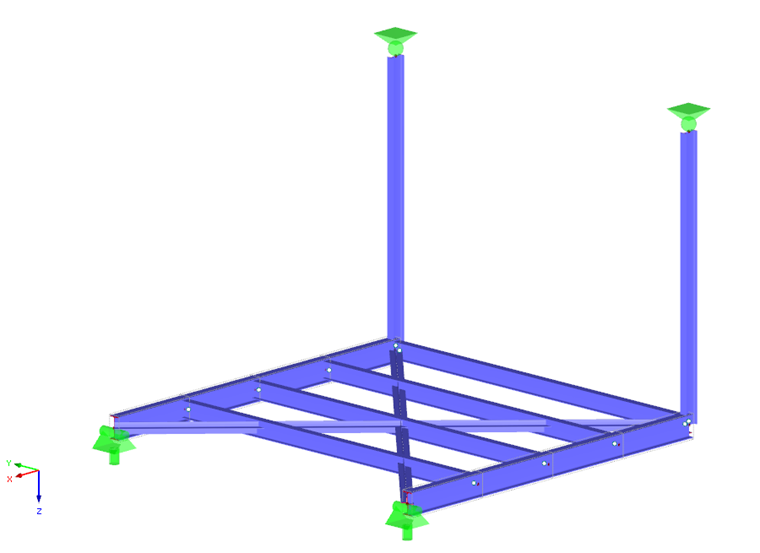
The (preliminary) design by using the Rf-/STEEL EC3 add-on module resaulted in a main beam cross-section IPE220-S235JR and a cross-section of the platform beam IPE180-S235JR. The hangers are performed as IPE160-S235JR due to design factors. The stiffening of the platform should not be taken into account further here.
Figure 04 shows the fin plate connection with its most important dimensions. More dimensions will be probably indicated during the design. The internal forces of the connection result in:
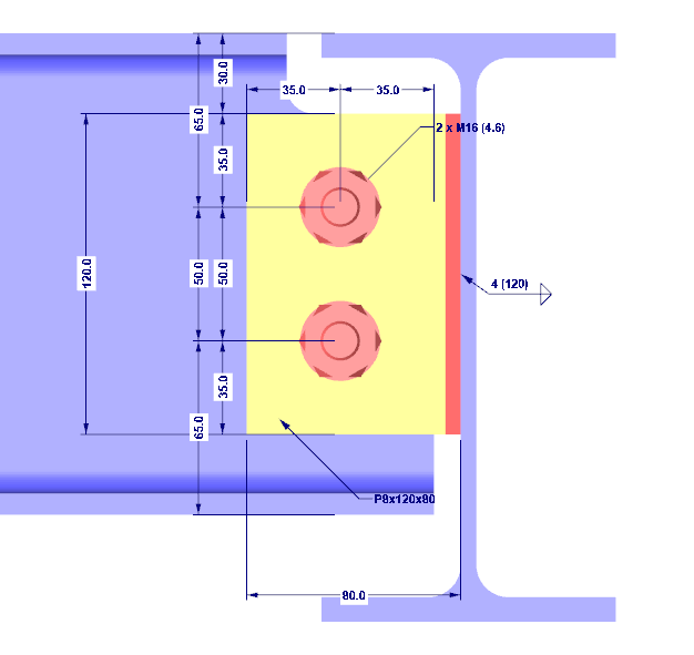
Before the design will be carried out in detail and partially explained, an obvious demand should be mentioned first: the height of the fin plate has to be smaller than the height of the secondarys beam. This demand should avoid the contact between the connected beam and the supporting structural components. The first design component pursues this aim which will be shown in the following.
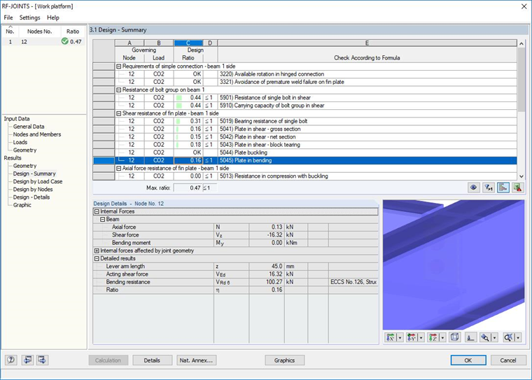
Available rotation in a pinned connection:
This is one of those designs that are easily skipped in design practice, but it ensures that a pinned connection can be assumed where one has been assumed when calculating the internal forces. For this design, a rotation point in the geometric center of gravity of the bolt layout is assumed. An angle is then calculated from which contact occurs between the girder flange and the supporting structural component (here, the main girder web).
Contact is basically possible.
The connection can absorb the occuring rotations of 0.45°, the design is fulfilled.
Prevention of premature weld failure:
Basically, the design of welds has to be carried out according to Section 4 of EN 1993-1-8 [1]. In case of relatively small loadings, compared to the shear resistance of the connected beam, the necessary welds may become very thin. In this case, the weld resistance is often smaller than the resistance of the other components. As a result, the possible failure of the connection is characterized by a brittle failure of the weld. The connection has almost no ductility.
The selected weld thickness was assumed with 4 mm. The criterion is thus fulfilled.
Shear failure of the single bolt:
The only difficulty of this design is the correct distribution of the internal forces of the connection over the single bolts. In general, the distribution of the forces is described in several textbooks, so that it is not further discussed here.
Ductile shear failure of the bolt group:
This design condition should ensure that a plastic redistribution of the internal forces from the actual state to the design state can take place. This criterion should never become governing, this means that the maximum utilization ratio should occur at this design.
Hole bearing failure of a bolt hole in the fin plate:
Since the number of shear planes at a fin plate connection is always 1, the force components correspond to those of the shear failure. A recalculation is therefore not necessary.
Shear failure in the gross cross-section of the fin plate:
Shear failure in the net cross-section of the fin plate:
Block shear resistance of the bolt group in the fin plate:
The design against block shear resistance of the bolt group is a standard design like the shear and bearing resistance design of the single bolt, which is not explained further here. For a more detailed presentation of the design formulas, please refer to various textbooks.
Bending failure of the fin plate:
This failure mechanism may not occur in many cases. Since the effort for the calculation of the resistance of the fin plate bending is rather manageable, a resistance value is normally always calculated. However, it can be ruled out that this failure mechanism can become governing if the height of the fin plate exceeds 2.73 times the lever arm z. In this case, the bending resistance is always higher as the one for shear failure in the gross cross-section of the fin plate.
Fin plate buckling:
This design is often forgotten in design practice. It might happen that it just becomes the governing design at unfavorable geometric conditions. This design derives from the old British steel construction regulation BS 5950-1 [3] from 2000. For closer examinations, it is referred to this regulation as well as the commenting literature.
The buckling resistance (actually lateral-torsional buckling resistance) thus depends on the strength of the fin plate for lateral-torsional buckling, which in turn depends on the slenderness of the plate. The value of the strength can be taken from tghe British regulation BS 5950-1 [3] in Table 17, while it must be mentioned that structural steels of the strength S235 are not or rarely used in the United Kingdom; that is why no values are explicitly contained for this steel. However, the values of S275 and the yield strength S235 can be used.
Theoretically, buckling design would be thus possible, which is, however, not considered appropriate. It seems to be better to fully exclude this type of failure of the fin plate. It can be taken for granted if the following design is met.
Tension failure of the fin plate in the gross cross-section:
This design is only necessary for occuring normal forces in the connection. Despite the small loadings from normal force, which can be classified as negligible, the design is performed for the sake of completeness.
Tension failure of the girder web in the net cross-section:
Strength design of the beam in the notched area:
This design becomes often governing when notches are necessary at both sides of the beam. It has to be berified here that the occuring bending moments and the shear forces in the notched are of the beam can be absorbed safely.
The shear force can be neglected in further design. Theoretically, an equivalent stress design can be performed, which is, however, neglected in the following text. Only the normal stress from the bending moments and the normal firces is determined and verified.
Hole bearing failure of a bolt hole in the girder web:
The acting forces correspond to those in the fin plate. However, the resistances have to be recalculated due to the different plate thicknesses.
Shear failure in the gross cross-section of the girder web:
Shear failure in the net cross-section of the girder web:
Block shear resistance of the bolt group in the girder web:
Tension failure of the girder web in the gross cross-section:
This design is only necessary for occuring normal forces in the connection. Despite the small loadings from normal force, which can be classified as negligible, the design is performed for the sake of completeness.
Tension failure of the girder web in the net cross-section:
Bending failure of the main girder web:
This design is necessary for one-way and two-way, but unequally loaded fin plate connections at a column web. This design should also be performed if a fin plate is only welded to a girder web. This is surely not the general rule, since the fin plate will be welded to at least one main girder flange in design practice. In this example, such a connection configuration has been deliberately selected to briefly show this design.
Due to the low normal forces, the design would not be considered in design practice as well, since a failure of the main girder web can be excluded from the outset.
At this point, the connection is design is successfully completed. All design conditions are fulfilled.
It should be emphasized here that the design contained only one load combination. Theoretically, the design has to be performed individually for all possible design combinations, which would be very extensive. In design practice, it is often the case that the internal forces from an enveloping are used, which may lead to very uneconomical connections in the worst case.
Influence of Connections on the Stability of the Component
Finally, the biggest problem that occurs with fin plate connections, as well as with other pinned connection types, is mentioned: the partially large deviation from a lateral and torsional restraint. This deviation is, in contrast to rigid connections, often incorrect and thus of significant importance in respect of safety.
The following text will not show the one correct design method for this problem, but rather, how a design engineer might handle it.
In steel construction, it often occurs that the engineer in charge of the beam design does not design all connections of the structure. He will ususally design the column bases as well as the main connections of the structure and hand over the secondary connections to the executing company. The engineers and designers working for this company know best which connections suit for their technology in manufacture and assembly.
The big problem in this working procedure is that the designer in charge of the beam design hardly thinks about if his secondary beams are connected according to his assumptions. He/she might often assume a lateral and torsional restraint at the beam end for platform beams bearing risks for lateral-torsional buckling, which at times might be a problem for the designer of the connections. The question here is what the designer could already do when designing the beam to simplify the work for the subsequent designer of the connection.
The old German steel construction standard DIN 18800-2 offered the possiblity to consider beam notches in lateral-torsional buckling analysis by assigning the beam coefficient n = 2.0 to the notched beam (in contrast to the unnotched beam n = 2.5). In the current Eurocode design for lateral-torsional buckling, this would correspond to a classification to a more unfavorable lateral-torsional buckling curve (for example, from buckling curve b to c). Such a consideration of a notch is not provided in EN 1993-1-1 [2]. This reclassification of the buckling curve for pinned secondary beams of a steel structure should always be performed, as this gives the subsequent connection designer the option of not necessarily having to create a lateral and torsional restraint. Another possibility of this reclassification of the buckling curve would be to limit the ratio of the secondary beams for lateral-torsional buckling to a certain value (for example, 80%).
Within the framework of connection design, the responsible designer has to verify the design of the secondary beam for the lower connection stiffness anyway, which is then only possible, if he has some tolerances from the original planning. How this design might look like is the decision of the designing engineer. Unfortunately, the engineering standards offer no assistance.
The design of the beam taking into account the lower connection stiffness can be basically performed in two ways: either by direct consideration in the support by using a torsion spring or by means of table values or diagrams to determine the elastic critical buckling moment.
The second case is the preference provided that an equivalent member design should be performed manually. Since the design process is not covered in particular by this article, it is only referred to useful references. Highly recommendable are the articles [5], [6] and [7]. Unfortunately, the corresponding research report of DASt to [6] and [7] has not yet been published which might be the most useful source in German concerning this difficulty.
The possibility to consider an appropriate torsion spring is certainly the solution approach if the design should be performed with the general method according to Section 6.3.4 of EN 1993-1-1 [2] or with the calculation according to the second order torsional buckling theory. To get these spring parameters, a calculation with the FE method (for example, RFEM) is possible.