Type 1: Modeling in Same Plane
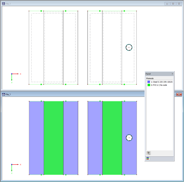
Option 1 follows the approach to model both surfaces in the same plane. Assuming there is a large rectangular surface (blue) that has to be reinforced by an additional surface (green). Both surfaces have the same Z-coordinates.
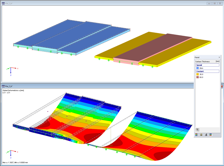
With a view of the FE mesh of the entire structure as well as the individual surface components, it becomes clear that each surface is meshed with itself.
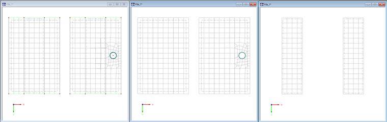
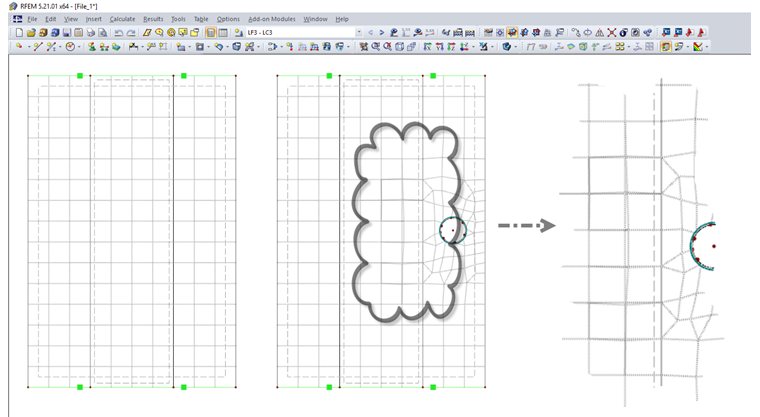
In the structure on the left, the elements of both surfaces are congruent. This is not the case in the right system. In this case, the FE mesh of the large surface is influenced by other elements integrated into the surface.
To illustrate the different effects, we assign a very soft material to the small surfaces. Additionally, only the small surfaces are stressed in order to better represent the behavior in relation to the large surfaces.
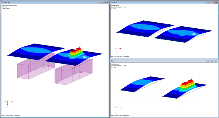
Due to the congruent FE mesh, the surfaces of the left system act like they are glued. Consequently, the deformations are identical. The situation is different in the right system. Due to the distortion of the FE mesh of the principal surface, the coordinates of the FE nodes are only identical to those of the small surface in some cases. A force transmission takes place only in these points. This also explains the local deformation peaks of the small surface in the middle region.
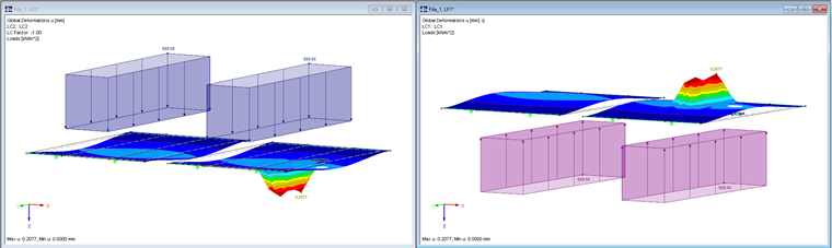
If we change the sign of the loading, it is also clear that there are no top or bottom surfaces due to the missing contact definition. Both surfaces can penetrate without force at the locations where they are not connected by congruent FE nodes.
Conclusion
Real models are usually more complex than the examples shown here. The FE mesh is even more influenced by the more irregular geometry, which may lead to unpredictable connections or releases between the surfaces. In the areas where the surfaces move independently of each other, it is also impossible to define contact conditions. Therefore, modeling by means of this method should be avoided.
Type 2: Adding Surface Thicknesses
If both surfaces consist of the same material, it makes sense to combine them by adding the thicknesses in a surface. This may require a division of the principal surface, but it is fundamentally relatively easy to implement. In the example, a 30-millimeter-thick steel plate was reinforced with another 30 mm plate. To the left, a model with solid elements is shown for verification.
Due to the simplified modeling, it is, of course, impossible to precisely consider the interaction of the surfaces.
Type 3: Modeling with Contact Solid
If the interaction between both surfaces plays a governing role, it is possible to use a contact solid. For this, both surfaces should be defined in their centroids. The resulting distance corresponds to the thickness of the contact solid. The contact conditions can be assigned to it afterwards (for example, failure under tension, friction, and so on).
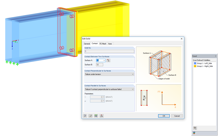
Modeling using an end plate joint is shown in the video.