Generating Solids
The previous chapter describes how existing surfaces can be used to create solids or casings. If you want to generate a completely new solid, however, RFEM provides special functions for creating 3D objects: First, the surfaces are created (rectangle with fillets, semicircle, and so on). In a second step, extrude the surfaces in relation to a point or a plane.
Extruding a surface in relation to a parallel plane
The function is accessed via the menu Insert → Model Data → Solids → Graphical → Extrude to Parallel Plane or the corresponding list button in the menu bar.

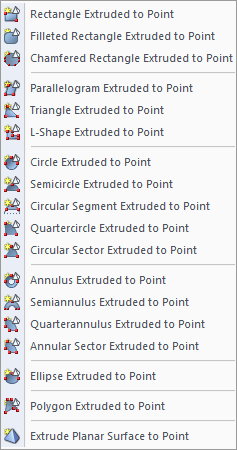
The menu contains a multitude of planar surface shapes that can be defined graphically and then extruded parallel to the surface plane.
The functional principle is similar to the graphical input of surfaces (see Chapter 4.4): First, define the material and stiffness in a dialog box. Then you can create the surfaces in the work window by clicking the definition points.

Once the base area is defined, specify the parameters for creating the solid in the Extrude dialog box.

The Height h can be entered directly in the dialog box or determined graphically with the mouse. The projection direction is always orthogonal to the plane of the base area.
By entering a value in the Tapering dialog section, you can create a parallel cover or base area with inclined sides. The angle β describes the inclination towards the projection direction.
In addition, the Material of the new solid must be specified.
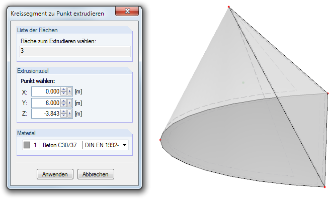
Extruding a surface in relation to a point
The feature is accessed via the menu Insert → Model Data → Solid → Graphical → Extrude to Point.
The menu contains a large number of planar surface shapes that can be defined graphically and then extruded in relation to a point.
The functional principle is similar to the extrusion of the object in reference to a parallel plane (see above): First, define the base area graphically. Then you can enter the extrusion's projection point in the Extrude dialog box or define it graphically.