


Members
Continuous Beam
RFEM creates a continuous beam with supports, irregular spans, and a uniform cross-section. Optionally, load cases and result combinations are created as well.
2D Frame
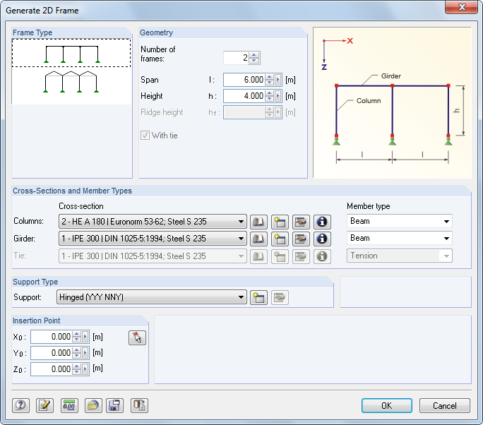
Before you enter geometrical data and cross-section properties, select the Frame Type. The columns of the planar frame receive equal support conditions.
Tapered 2D Frame
The planar frame must be defined by its Geometry and Cross-Sections. Tapers, crane runway brackets, and eccentric joints are possible. Loads can be generated as well. The [Details] buttons provide access to the generator parameters. The frame position is important for load determination.
2D Truss
In the list, specify the Type of truss and the arrangement of the Diagonals. Then you can define the Parameters, Cross-Sections, and Member Types.
Grid
This generator creates models that have a uniform grid (for example, girder grillage). They do not need to be constructed with right angles as shown in the dialog graphic; any spatial quadrangle models are possible across the four corner points. To create a “real” beam grid, the model type should be set to 2D - in XY in the model base data (see Chapter 12.2). You can also use the [Details] button to generate irregular grids.Column
In the Type dialog section, define if a center or corner column is generated. If you want to generate Loads, you have to specify their Effective Widths and Correction Factors.
For generating a gable column, the span a is required for the influence range in the longitudinal direction of the hall. The factors f1 and f2 are used to scale the geometric widths b1 and b2 for the static model or to fulfill specific code requirements (e.g. load increment factors for individual design checks).
Roof Generators
The Roof menu item provides three roof generators, which you can use to generate planar roof systems including loads (see following figures).
![]()
The [Settings] buttons in the roof dialog boxes help you to determine wind and snow loads (see Figure 11.155).
Roof → Collar roof
Roof → Rafter roof
Roof → Purlin roof
Fish Beam
To generate fish-bellied girders, which are mainly used in timber construction, the rectangular and ITS cross-section types (symmetric I-beams) are available for selection in the Cross-section type list.
3D Frame
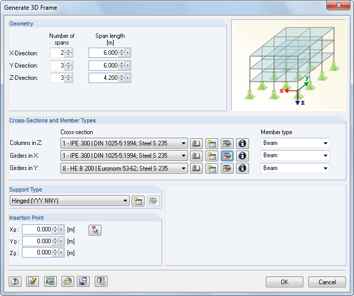
Use this generator to create regular frame models. The columns of the frame receive equal support conditions.
3D Hall
This extensive generator creates a complete hall, including loads. Four dialog tabs are provided: Geometry/Support manages the system geometry, while Division/Arrays regulates irregular grid spacing and the arrangement of arrays. In the remaining two tabs, the Cross-Sections and Loads are defined.
3D Truss
You can use this generator to create a spatial load-bearing structure according to the Bernauer system.
3D Cell
This generator creates a spatial cell with several fields. Use the button shown on the left to open another dialog box where you can define openings as well as the grid arrangement for irregular field spacings.
Straight Stairway
In the list, select the Type of stairway, which determines the remaining parameters.
Spiral Staircase
Line
This function allows you to generate straight lines based on new or existing nodes. It is also possible to create only nodes that lie on an imaginary straight line.
Arch
First, the type of arc must be specified: circle, parabola, hyperbola, or catenary. Points A and B represent the two edge nodes of the arc, while point C controls its arrangement. The sag is specified using the stroke. The parameter L specifies the length of a catenary. This interacts with the heights h1, h2, and h3.
The Parameter describes the constant a in the following equation of the catenary curve:
- where vx or vy: displacements in x or y
The larger the number of members is, the more precisely the arc is modeled as a polygonal chain.
Circle
The circle arc or full circle is defined by the Radius and Angles. The object is created around a center point that can be selected anywhere in one of the global planes.
Sphere
The larger the number of Planes and Meridians is, the rounder the shape of the sphere will be. The approximation to the spherical shape is achieved by polygon chains, with each segment corresponding to a member.
Bracings in Cells
Cells are defined by four corner nodes, enclosed by members on all sides and placed in a plane.
In the generator dialog box, specify the Members of Bracing and the Cells for Bracing or use the buttons to select them in the work window by clicking the cell crosses.
Virtual lines allow you to close cells so that bracings can also be created between wall supports, for example.