


The settings in the Main tab are divided into several sections.
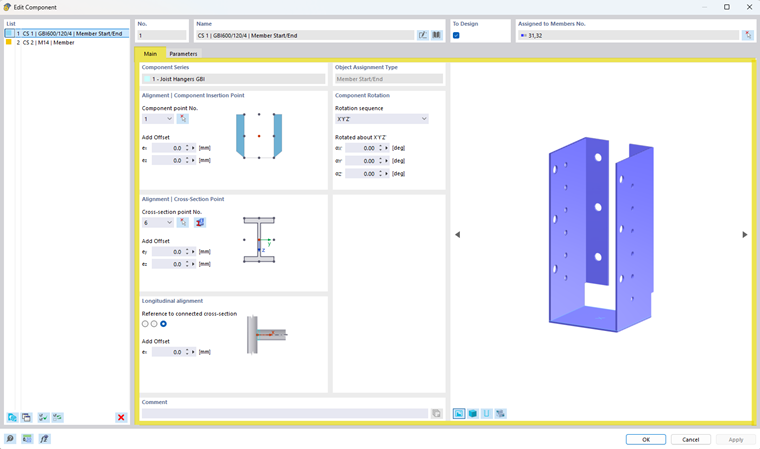
Component Series
This section displays the component series from which the selected component originates.
Object Assignment Type
The object assignment type determines to which model object the component is assigned.
Depending on the component series, the following assignments are possible, for example:
- Member
- Member Start
- Member End
- Member Start/End
The object assignment type is specified by the component series and determines the available input boxes as well as the component’s position in the model.
Component Rotation
The component rotation settings allow you to adjust the orientation of the component.
The following parameters are available:
- Rotation sequence
- Select the order in which rotations are performed (for example, X'Y'Z')
- Rotations
- αX'
- αY'
- αZ'
Angles can be specified in degrees.
You can change the units at any time using the
 button in the lower-left corner of the dialog box.
Alignment | Component Insertion Point
This section defines the component’s insertion point relative to the associated object.
The following settings are available:
- Component point No.
- Select the insertion point of the component:
- Select it in the preview image
 or from the drop-down list
- Select it in the preview image
- Select the insertion point of the component:
- Add Offset
- Define an additional offset for the component using the coordinates:
- ex
- ez
- Define an additional offset for the component using the coordinates:
The schematic display shows the currently selected insertion point of the component.
Alignment | Cross-Section Point
This section defines the location of the component relative to the cross-section of the assigned member.
The following settings are available:
- Cross-section point No.
- Select a defined reference point on the cross-section
- Select it in the preview image
or from the drop-down list
- Select it in the preview image
- Select a defined reference point on the cross-section
- Add Offset
- Additional offset in
- ey
- ez
- Additional offset in
You can also navigate directly to the cross-section properties using the
 button.
The schematic display shows the location of the selected cross-section point.
Longitudinal Alignment
Longitudinal alignment defines the orientation of the component along the assigned member.
Here, you can specify which connected cross-section the component should be referenced to. Furthermore, an offset in the member direction can be defined using the parameters ex.